Method of minimizing cross contamination between clean air rooms in a common enclosure

a technology of clean air and common enclosure, which is applied in the direction of auxillary pretreatment, heating types, separation processes, etc., to achieve the effect of increasing the portion of refiltered air and increasing the efficiency of the filter

Active Publication Date: 2007-04-26
SPENGLER CHARLES W
View PDF7 Cites 6 Cited by
  • Summary
  • Abstract
  • Description
  • Claims
  • Application Information

AI Technical Summary

Benefits of technology

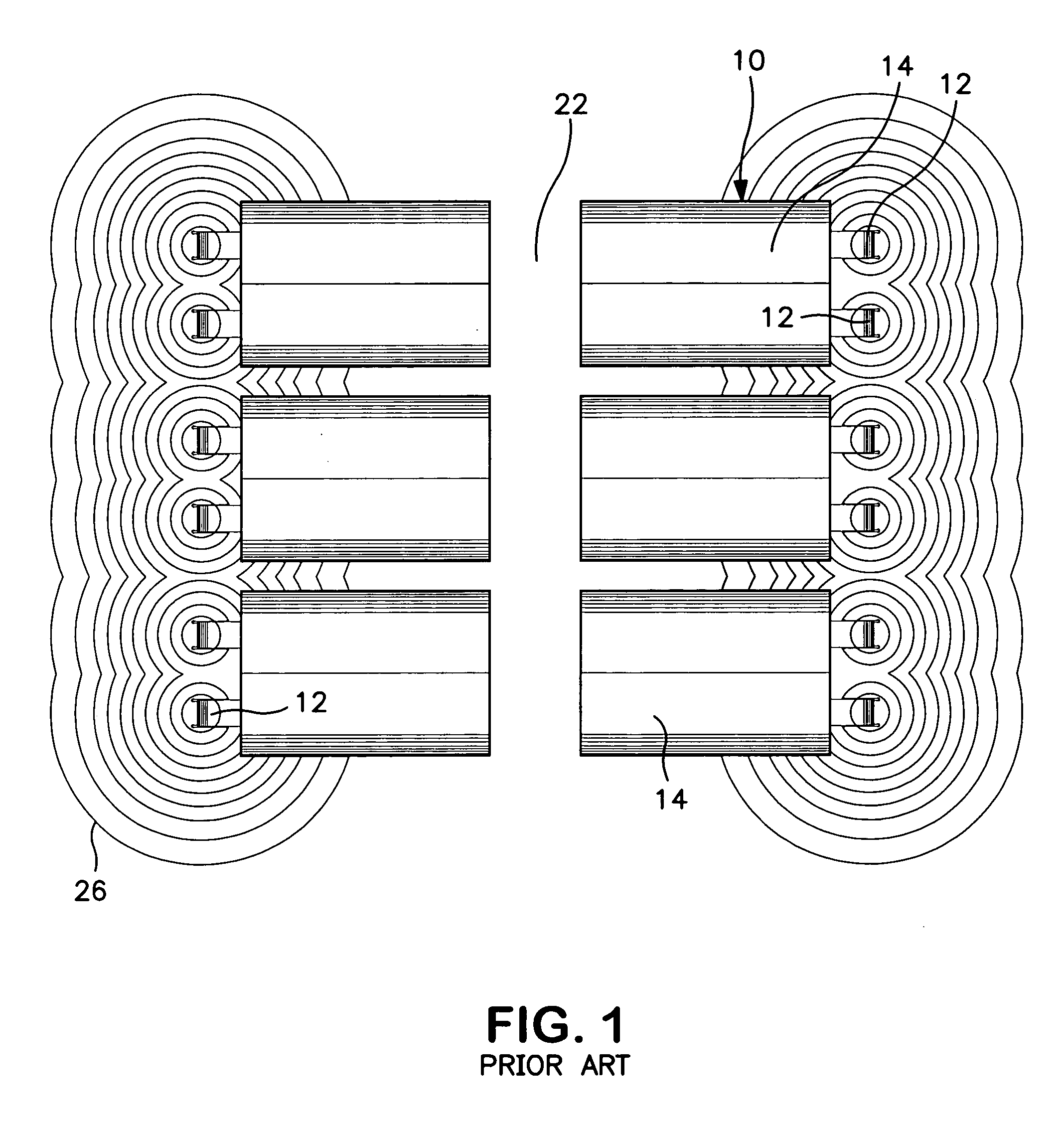
[0007] It has been discovered that operation of the clean room blowers results in air previously filtered and escaping from the rooms being drawn back into the blowers, along with ambient air from the enclosed structure. With continuous operation, the proportion of previously filtere

Problems solved by technology

It has been discovered that operation of the clean room blowers results in air previously filtered and esc

Method used


Image

  • Method of minimizing cross contamination between clean air rooms in a common enclosure
  • Method of minimizing cross contamination between clean air rooms in a common enclosure
  • Method of minimizing cross contamination between clean air rooms in a common enclosure

Examples


Embodiment Construction

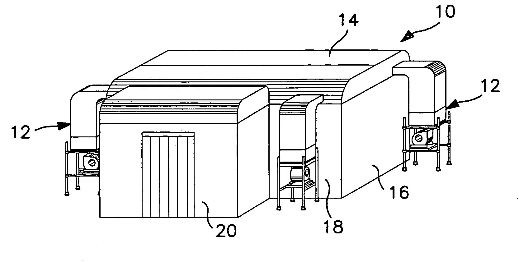
[0018] Referring now to the drawings in detail, FIG. 1 shows a conventional arrangement of a group—in this case, six—of portable clean air rooms 10 arranged in two parallel rows and with each clean room equipped with two generally identical blower units 12 located at the end wall opposite the access corridor 13 between the two rows. It is pointed out that the prior art clean air rooms that employed such arrangements may only employ a single blower unit or as may as three blowers for each clean air room in a group. The clean air rooms 10 may be of the type disclosed in my prior U.S. Pat. No. 4,804,392 mentioned above, with each room 10 consisting of an open, self supporting tubular framework covered with vinyl sheet material forming a top wall 14, end walls 16 and sidewalls 18. An access opening (not shown) in one sidewall or end wall facing corridor 22 is enclosed by an air lock entrance 20, as best seen in FIG. 2.

[0019] The in-line arrangement of the clean rooms 10 in two spaced p...


PUM

PropertyMeasurementUnit
Fractionaaaaaaaaaa
Fractionaaaaaaaaaa
Fractionaaaaaaaaaa

Abstract

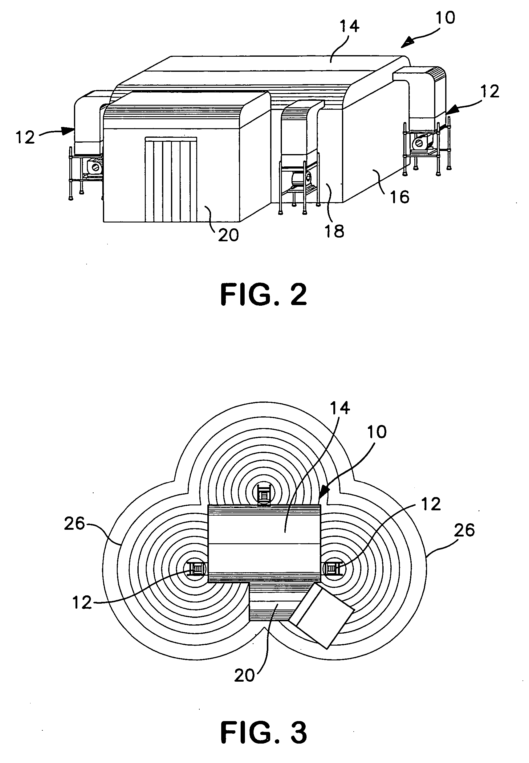
A method of operating a plurality of clean room in a compound within a common enclosure and supplying each room with filtered air by a blower-filter unit by arranging the clean rooms and the blowers connected thereto in two parallel spaced rows with a corridor therebetween, and permitting filtered air to escape the clean rooms from beneath the walls of the clean rooms. Continuous operation of the blowers produces a bubble-like volume of air surrounding the blowers which consists primarily of clean, recirculated air escaping from the clean rooms. By arranging the clean rooms and blowers so that the clean air bubble produced by each blower overlaps the bubbles produced by at least two other blowers, the entire compound can be contained in a highly purified atmosphere consisting primarily of recirculated filtered air. A portion of the air from one or more clean rooms may be discharged in an upward direction through an opening in its top wall.

Description

BACKGROUND OF THE INVENTION [0001] 1. Field of the Invention [0002] This invention relates to the operation of multiple clean rooms in a compound within a common enclosure structure, and more particularly to a method of minimizing contamination in the rooms and minimizing cross contamination between the rooms. [0003] 2. Description of the Prior Art [0004] It is well known, particularly in life sciences laboratories, to provide a plurality of individual clean rooms in a larger common enclosure structure, or room. The clean rooms may be relatively rigid enclosures or portable structures including a self-supporting framework covered with a flexible sheet material such as a vinyl sheet, with the individual enclosures having one or more blower-filter units (hereinafter, blowers) for continuously providing a flow of air through high efficiency particulate air filters (HEPA filters) to the room. One known vinyl covered clean room arrangement is disclosed, for example, in my prior U.S. Pat....

Claims


Application Information

Patent Timeline
IPC IPC(8): B01D50/00
CPCF24F3/161F24F11/0001F24F3/167
Inventor SPENGLER, CHARLES W.
Owner SPENGLER CHARLES W
Why Eureka
Try Eureka