Automatic sizing one-handed locking pliers

a technology of locking pliers and one-handed sizing, which is applied in the field of mechanical tools, can solve the problems of cumbersome and time-consuming task of adjusting the locking pliers, requiring both hands of the mechanic, and tedious us

Active Publication Date: 2007-04-26
HUNTER MARC W
View PDF19 Cites 3 Cited by
  • Summary
  • Abstract
  • Description
  • Claims
  • Application Information

AI Technical Summary

Benefits of technology

[0011] A final aspect of this invention allows the locking plier to remain loosely gripped around the work piece when the pliers have been released into their open position. This is a particularly useful feature of the locking plier mechanism of the instant invention since it allows the workman to remove the wrench, with one hand, at the workman's convenience. This feature eliminates the wrench falling on the workman if he is an awkward position. Further in connection with this capability, another advantage of the invention is that releasing the pliers can be accomplished with exertion of a relatively light force, even when the pliers are set to a high gripping or clamping force, as the required release force is not a function of the gripping force. Thus, a further object of the invention is the capability to more easily release the pliers, yet still provide a loose gripping force for holding the pliers on a work piece.
[0012] Other and further objects of this invention will become obvious upon reading the below described specification. BRIEF DESCRIPTION OF THE DEVICE
[0013] The locking pliers device described has the basic structure of a locking pliers, including an upper fixed jaw connected to an upper body handle and a lower pivoting jaw connected to the upper handle by a middle lever. A lower pivoting handle is connected to the middle lever and the lower jaw. An improvement to existing locking pliers includes an adjusting screw-type mechanism that is placed near the pivot point between the lower handle and middle lever to adjust the grip strength (or clamping force) of the locking pliers. Within the upper body handle is another improvement, a workpiece automatic sizing and locking mechanism. The unique locking mechanism includes a tapered metal housing containing ball bearings that surround a locking rod (or plunger). The locking rod is spring biased towards the jaws and may be locked in place when the ball bearings are forced against the outer surface of the rod. The locking rod abuts the middle lever and pushes against it. A palm handle, located at the end of the body of the locking pliers, allows to the workman to release the locking rod by pushing the palm handle downwards. A thumb operated sizing lever is also located within the upper body and is connected by a linkage to the lower jaw. The pliers are sized and locked to a workpiece by opening the spring-loaded jaws with the thumb lever, releasing the thumb lever, and squeezing the lower handle towards the upper body. The thumb lever and locking rod automatically adjust the jaw size and lock the pliers to the workpiece. The lower paddle releases the jaws, and is configured so as to be operable with a relatively light force, but they remain lightly closed on the workpiece until the workman opens them by pushing on the thumb lever.

Problems solved by technology

Some of the problems with locking pliers include the fact that they are tedious in use, since iterative screw adjustments must be made to size the jaws to the part.
One such problem is that while the tools must be sized to fit the work piece, the sizing is usually done by a thumbscrew mechanism that requires both hands to operate the mechanism.
Another problem with the locking pliers heretofore known in the art is that the sizing of the pliers onto the work piece has a direct correlation to the hand pressure or gripping pressure used to lock the pliers onto the piece.
Another major drawback in the use of ordinary locking pliers is that the handgrip strength tensioning mechanism and the sizing mechanism require both hands of the mechanic.
Since both hands are needed to attach and tighten the pliers to the workpiece, the task of adjusting the locking pliers is both cumbersome and time consuming.

Method used


Image

  • Automatic sizing one-handed locking pliers
  • Automatic sizing one-handed locking pliers
  • Automatic sizing one-handed locking pliers

Examples


second embodiment

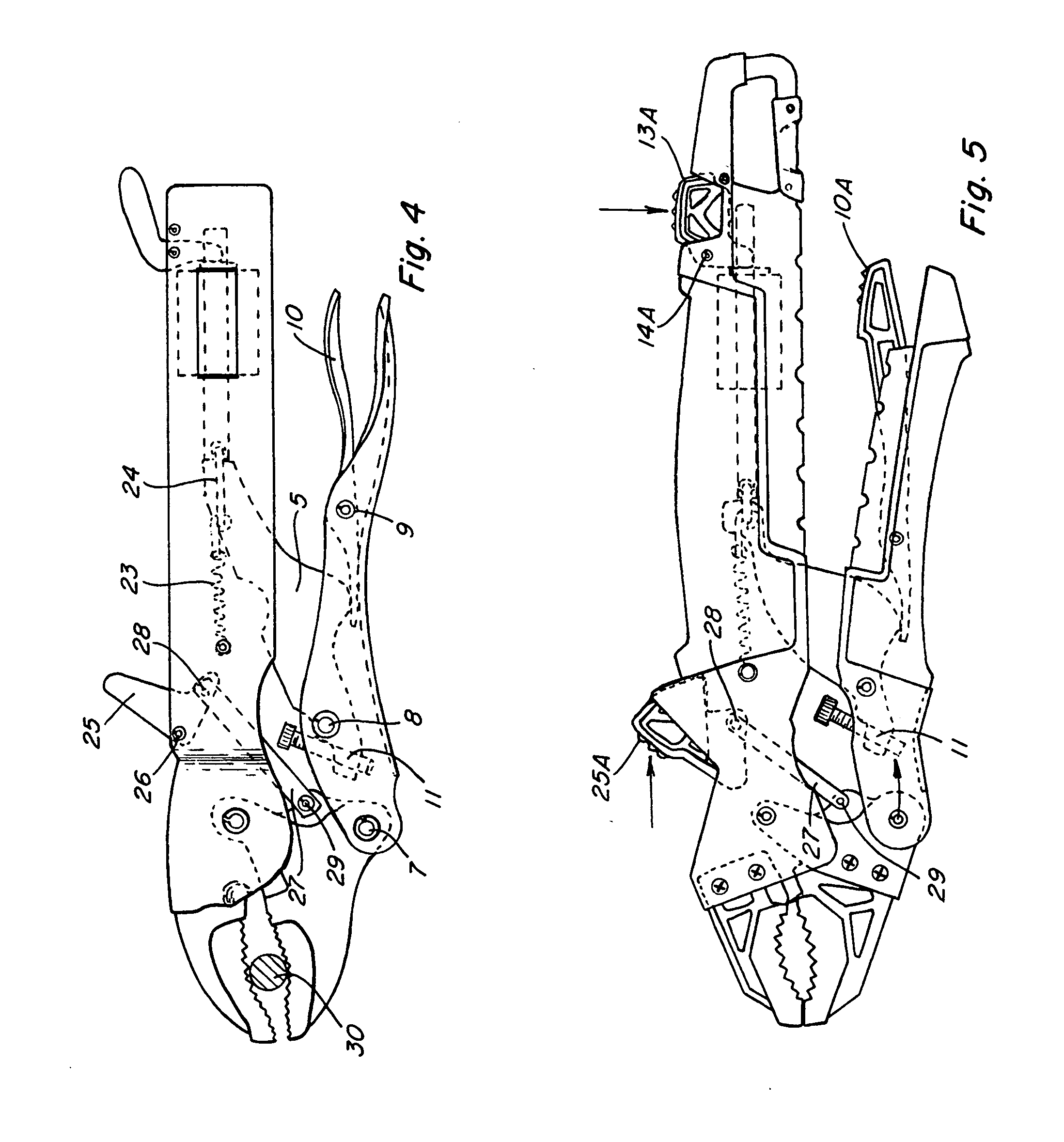
[0047] Another difference in the second embodiment is the use of an alternate thumb jaw piece 25A. In place of the pivoting boot 25, shown in the embodiment of FIG. 4, a sliding thumb jaw piece 25A is provided. The alternate thumb jaw piece 13A moves upwardly when the user slides the thumb jaw piece 25A upwardly. This action moves the linkage 27 upward, which opens the lower jaw 2. The thumb jaw piece 25A is designed to be pulled upward on a slant as shown in FIG. 5.

[0048] Alternatively, a second thumb jaw piece pivot could be provided such that the thumb jaw piece pivots when the piece 25A is depressed by the user's thumb. Depressing the piece 25A would pull the linkage 27 upwards, releasing the lower jaw.

[0049] In the embodiment in FIG. 5, a more ergonomically designed lower release paddle 10A also replaces the standard release paddle 10. While the second, alternate embodiment shown in FIG. 5 has the above slight modifications, the main and essential parts of the device remain th...

embodiment 36

[0052] Also in embodiment 36 in FIGS. 10 and 11, another alternative release paddle 10B replaces release paddle 10 and 10A shown above. Again, jaw 2 is pivotally connected to handle 3 at pivot point 6. Handle 4 is pivotally connected to jaw 2 at pivot point 7. Middle lever 5 is pivotally connected to handle 4 at pivot point 8. However, release paddle 10B is now pivotally connected to handle 4 at a pivot joint 42, closer to jaws 1 and 2 than the irregularly shaped humped portion of middle lever 5. Once the locking pliers have been locked onto a workpiece, they may be released by moving release paddle 10B upwardly, as denoted by arrow D, toward handle 3. The release paddle 10B pivots about pivot point 42. The surface of release paddle 10B comes into contact with the irregularly shaped humped portion of middle lever 5, which is forced thereby upwardly and toward the jaw end of the pliers. This motion releases the upper and lower jaws. As stated above, an advantage of this construction ...


PUM


Abstract

An automatically adjustable locking pliers or tool includes a jaw fixed to a first handle and a jaw that pivots about the first handle. The pivoting jaw is connected to a lower tightening handle. A lever connects the tightening handle and first handle. A self-adjusting sizing and locking mechanism includes a thumb jaw sizing piece located near the jaws and movable to open the jaws so that they can be sized around a workpiece. When the thumb jaw sizing piece is released, the jaws automatically size and clamp lightly around the workpiece. The locking mechanism uses balls between a locking rod and a tapered surface. Locking occurs when the balls wedge between the rod and the tapered surface. A release cylinder is connected to a release paddle movable to unlock the mechanism. The sizing piece and locking mechanism are operable to automatically size and lock the pliers or tool.

Description

[0001] This application is a continuation-in-part of co-pending U.S. application Ser. No. 11 / 052,509, filed Feb. 7, 2005.BACKGROUND OF THE INVENTION [0002] This invention relates to the field of tools for mechanical work. More particularly, an automatically sized one-handed locking plier is presented. [0003] Locking pliers have been sold in their standard form for decades with little significant improvements. While the pliers perform wonderfully and are a staple in every toolbox around the world, certain improvements would make the locking pliers even more useful. Locking pliers differ from ordinary pliers in that they contain a mechanism to lock the jaws of the pliers onto the work piece. Many different types of locking pliers have been produced, and they are commonly known in the trade as Vise-Grips.RTM. or simply “locking pliers”. [0004] Some of the problems with locking pliers include the fact that they are tedious in use, since iterative screw adjustments must be made to size t...

Claims


Application Information

Patent Timeline
Patent Type & Authority Applications(United States)
IPC IPC(8): B25B7/12
CPCB25B7/123
Inventor HUNTER, ROBERT E.
Owner HUNTER MARC W
Why Eureka
Try Eureka