Method for controlling a bi-level apparatus, and bi-level apparatus

a technology of bi-level apparatus and bi-level apparatus, which is applied in the direction of sensors, diagnostics, applications, etc., can solve the problems of difficult to precisely detect the transition between inspiration and expiration, rough signal, and more nois

Active Publication Date: 2007-04-26
VYAIRE MEDICAL GMBH
View PDF21 Cites 49 Cited by
  • Summary
  • Abstract
  • Description
  • Claims
  • Application Information

AI Technical Summary

Benefits of technology

[0016] The additional inclusion of the actual pressure increases the reliability of the switching between inspiration and expiration mode. One aspect is here that no switching to the inspiration mode is to take place in the event of coughing or sneezing. The actual pressure hereby increases above the set pr

Problems solved by technology

In connection with bi-level apparatus it is technically difficult to exactly detect the transitions between inspiration and expiration by means of the airflow, because the pressure is to be changed exactly during these transitions.
It is also problematical that a derivative acts like a high-pass filt

Method used


Image

  • Method for controlling a bi-level apparatus, and bi-level apparatus
  • Method for controlling a bi-level apparatus, and bi-level apparatus
  • Method for controlling a bi-level apparatus, and bi-level apparatus

Examples


Embodiment Construction

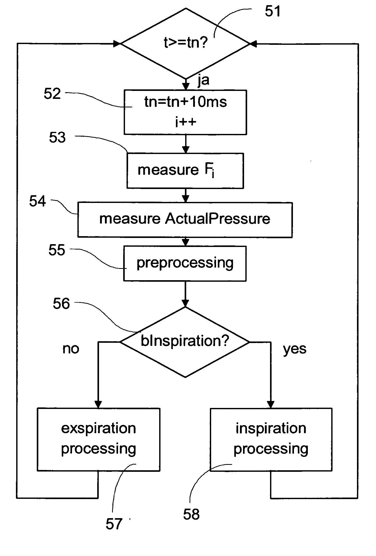
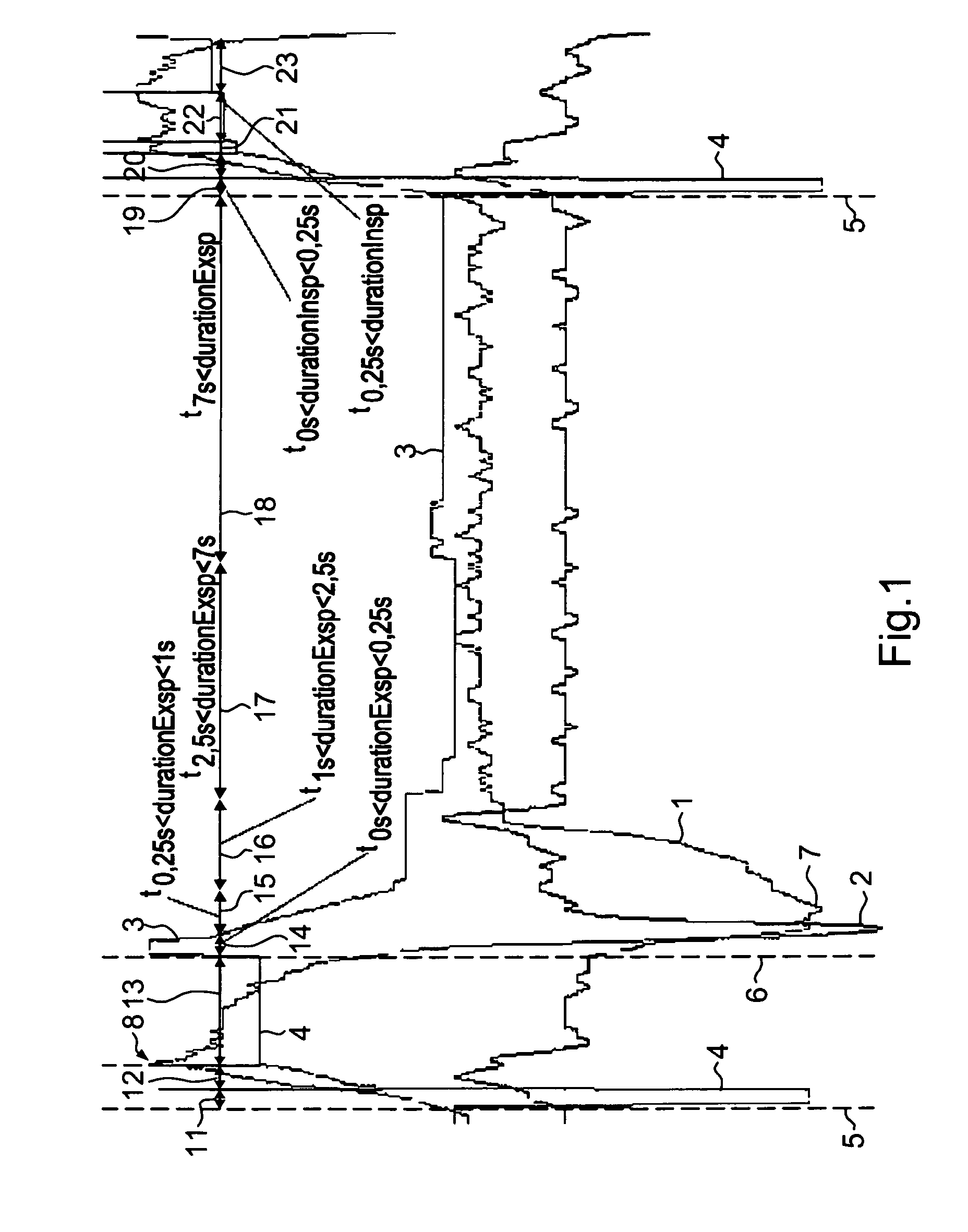
[0026]FIG. 1 shows a diagram depicting the timing of the airflow 1, the derivative of the airflow 2 and the expiration threshold value 3 and the inspiration threshold value 4. Moreover, different time domains were marked, which will be explained in more detail below in connection with the flowchart of FIGS. 5 to 8. The expiration phase was intentionally dragged on by the test person in order to represent all time domains provided in the method according to the invention.

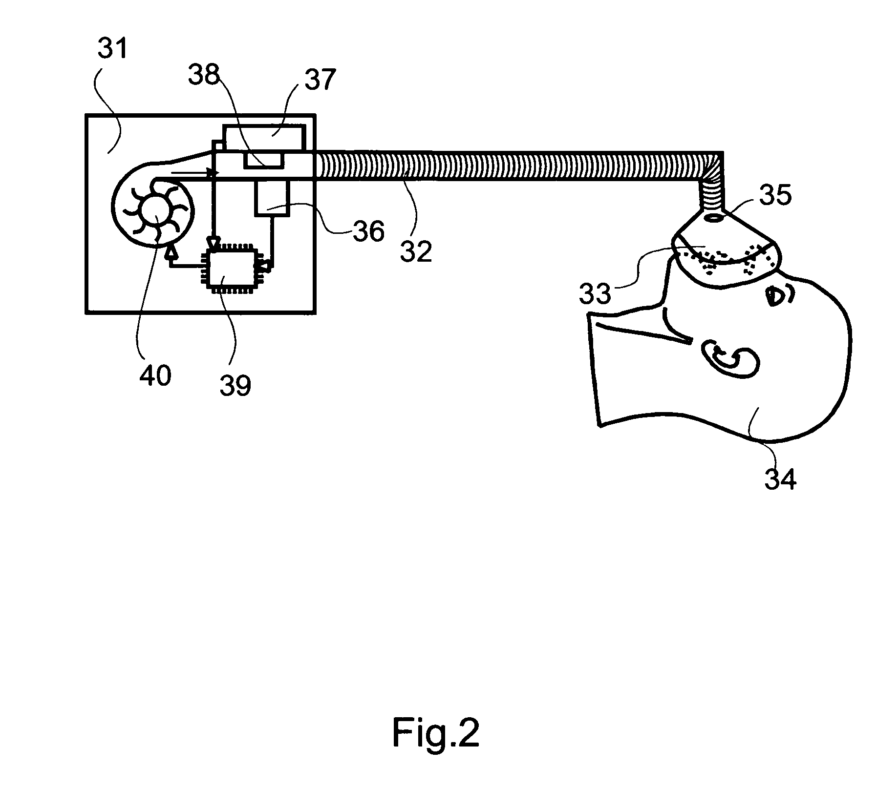
[0027]FIG. 2 schematically shows the hardware for an auto-CPAP- or a bi-level apparatus 31. A fan 40 conveys air and makes it available under an overpressure of up to 30 mbar. The air is administered to a patient 34 by means of a respiratory hose 32 and a mask 33. Air permanently escapes into the environment through the opening 35, so that exhaled air having a higher fraction of CO2 is flushed out of the opening 35. A pressure sensor 36 for measuring the overpressure generated by the fan 40 is mounted in the apparat...


PUM


Abstract

This invention relates to a method for controlling a bi-level apparatus. The method includes repeatedly measuring an airflow, choosing an expiration threshold value and choosing an inspiration threshold value. Switching to an inspiration mode takes place if the airflow is greater than the expiration threshold value in a comparison with the expiration threshold value. A switching back to the expiration mode takes place if the airflow is smaller than the inspiration threshold value in a comparison with the inspiration threshold value. Moreover, the invention relates to a bi-level apparatus for performing the method.

Description

CROSS REFERENCE TO RELATED CO-PENDING APPLICATIONS [0001] This application is a continuation of international application number PCT / DE2005 / 000534 (publication number: WO 2005 / 092414 A1) filed on Mar. 23, 2005 and entitled METHOD FOR CONTROL OF A BI-LEVEL DEVICE AND BI-LEVEL DEVICE and claims the benefit of the above-mentioned international application and the corresponding German national patent application number 10 2004 014 538.5 filed on Mar. 23, 2004 and entitled VERFAHREN ZUR STEUERUNG EINES BILEVEL-GERÄTS SOWIE BILEVEL-GERÄT the contents of which are expressly incorporated herein by reference.FIELD OF THE INVENTION [0002] The invention relates to a method for controlling a bi-level apparatus, and bi-level apparatus. Specifically, this invention relates to the reliable detection of inspiration and expiration despite the pressure fluctuations generated by the bi-level apparatus. BACKGROUND OF THE INVENTION [0003] Like the slightly less complex CPAP-apparatus, bi-level apparatus...

Claims


Application Information

Patent Timeline
IPC IPC(8): A61M16/00
CPCA61M16/00A61M2016/0021A61M2016/0036A61M16/0069A61M2016/0027A61M16/024
Inventor GABRIEL, STEPHANWHITEHEAD, ELLISGENGER, HARALD
Owner VYAIRE MEDICAL GMBH
Why Eureka
Try Eureka