Multidiameter wire cloth

Inactive Publication Date: 2007-04-26
BAKULA JOHN JAMES
View PDF8 Cites 11 Cited by
  • Summary
  • Abstract
  • Description
  • Claims
  • Application Information

AI Technical Summary

Benefits of technology

[0011] It is therefore an objective of the present invention to provide a wire cloth material which can be used to strain and / or separate materials placed upon the cloth.
[0013] It is a further objective of the present invention to provide a wire cloth material which will prevent ripping of the wire cloth material during material loading on the cloth.
[0014] It is a further objective of the present invention to provide a wire cloth material which is easy and cost effective to manufacture.
[0015] It is a further objective of the present invention to provide a wire cloth material that can be incorporated into a frame to provide a screen which will segregate material placed upon the frame.
[0016] It is also an objective of the present invention to provide a screen which incorporates a frame and a wire cloth material which will prevent ripping during operation, wherein the screen may be used in equipment commonly used in drilling and mining operations.

Problems solved by technology

This standardized diameter wire cloth, however, has significant drawbacks.
The first drawback of standardized diameter wire cloth is that the cloth provides insufficient capacity to resist structural loading which causes degradation.
The combination of the frame and the cloth, however, does not provide the necessary protection to stop ripping of the cloth.
Larger materials, however, either impact the wires in the wire cloth and then pass through the holes between the wires, or the materials impact the individual wires and fail to pass through the open area.
When the larger materials either impact the individual wires or impact the wires and fail to pass through the open area, the wires themselves sustain damage.
The damage caused by the impact is usually permanent and therefore further damage to the wires may cause individual wires to fail.
The additional load causes the adjacent wires to deform and similarly fail.

Method used


Image

  • Multidiameter wire cloth
  • Multidiameter wire cloth
  • Multidiameter wire cloth

Examples


Embodiment Construction

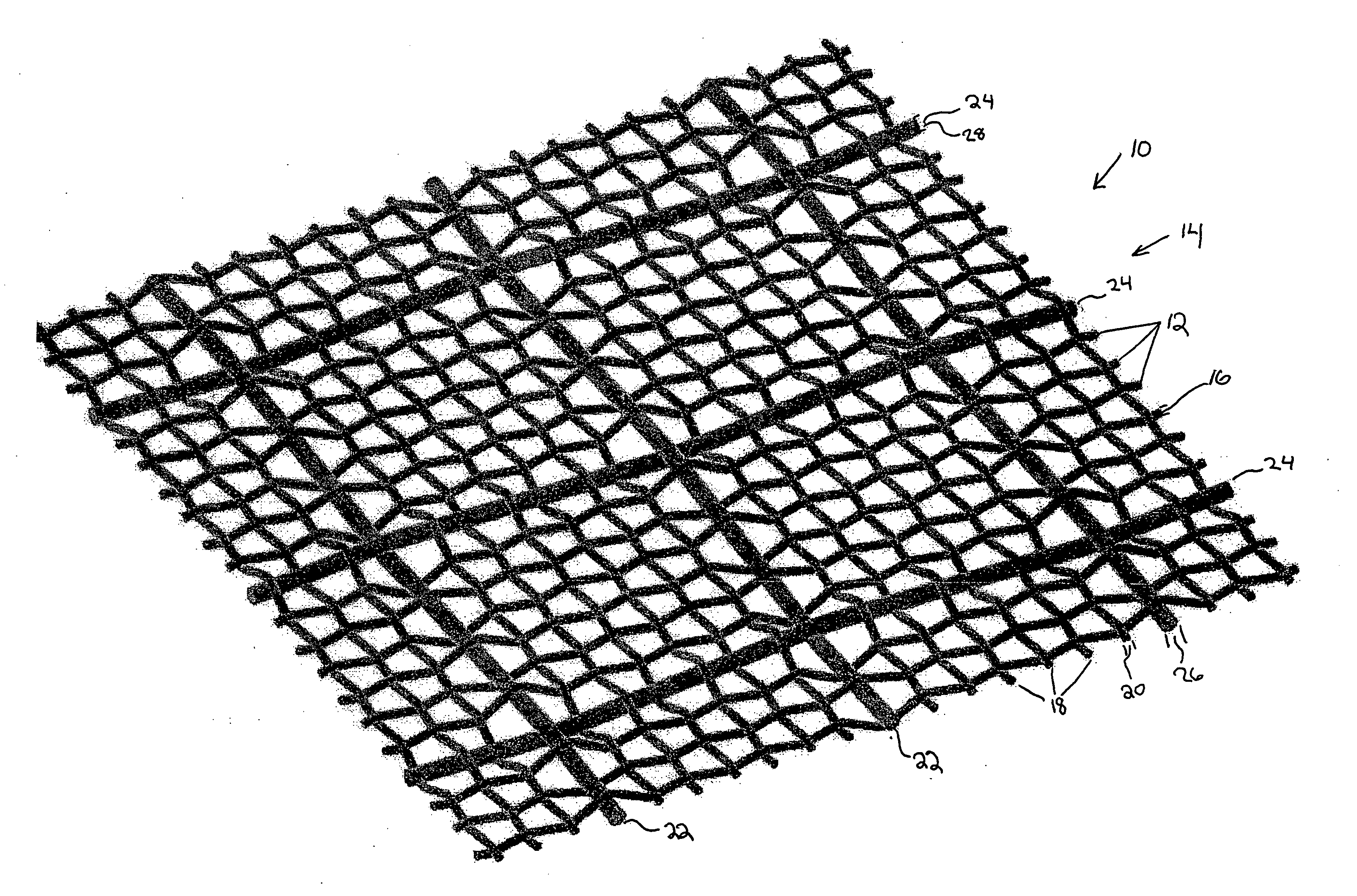
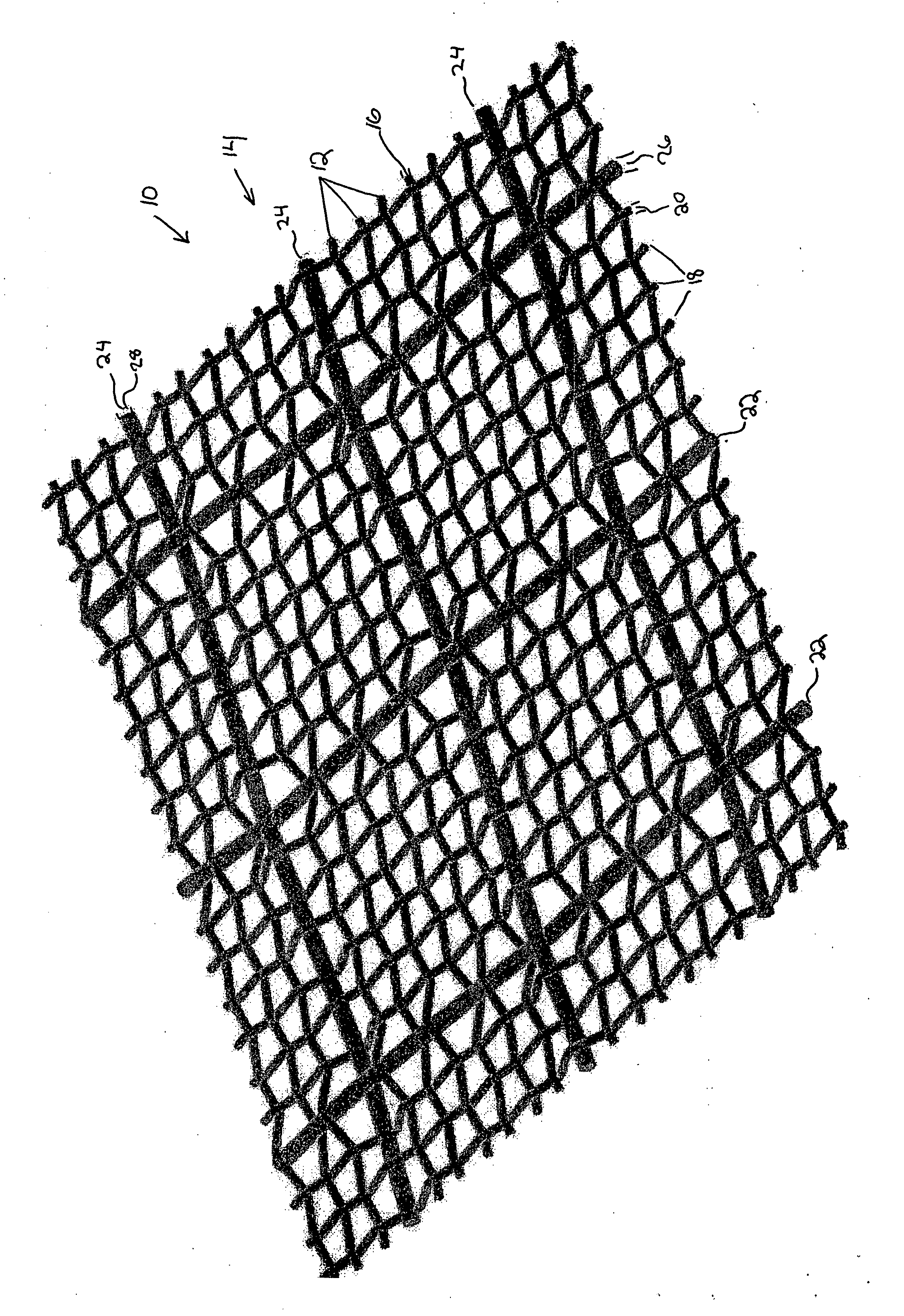
[0027] Referring to FIG. 1, a wire mesh cloth 10 is illustrated. The wire mesh cloth 10 has an arrangement of first wires 12 which extend in a horizontal direction 14. The first wires 12 are provided with a first diameter 16. The first diameter 16 is constant throughout all of the arrangement of first wires 12. A second arrangement of wires 18 is also provided with a constant second set of diameters 20. A third arrangement of wires 22 is further provided which are parallel in direction to the arrangement of second arrangement of wires 18. The third arrangement of wires 22 is interspersed in the second arrangement of wires 18 such that the third arrangement of wires 22 extend in a parallel direction to that of the second arrangement of wires 18. A fourth arrangement of wires 24 is also provided in an interspersed manner with the wires of the arrangement of first wires 12. The fourth arrangement of wires 24 extends in a parallel direction to that of the horizontal direction 14 of the ...


PUM

PropertyMeasurementUnit
Fractionaaaaaaaaaa
Fractionaaaaaaaaaa
Fractionaaaaaaaaaa

Abstract

A wire mesh fabric, having a plurality of wires running in a first parallel direction, the first plurality of wires having a first wire diameter; a second plurality of wires running in a second parallel direction, the second parallel direction orthogonal to the first parallel direction, the second plurality of wires having a second wire diameter; a third plurality of wires running in the second parallel direction, the third plurality of wires interspersed in the second plurality of wires, the third plurality of wires having a third wire diameter, wherein the third wire diameter is greater in diameter than the second wire diameter; and a fourth plurality of wires running in the first parallel direction, the fourth plurality of wires having a fourth wire diameter, wherein the fourth wire diameter is greater in diameter than the first wire diameter.

Description

FIELD OF THE INVENTION [0001] The present invention relates to wire mesh cloth. More specifically, the present invention provides a wire mesh cloth which has constituent wires with differing diameters. BACKGROUND INFORMATION [0002] Wire cloth is used for various functions such as, for example, providing a barrier between different components. Wire cloth is also used to provide a component to strain or separate materials of different sizes. [0003] Wire mesh cloth that is used for straining and / or separating materials is produced with a standardized (common) wire diameter throughout the cloth weave. This standardized diameter for the wire strands comprising the cloth allows the cloth to be manufactured in a uniform manner with minimal cost. This standardized diameter wire cloth, however, has significant drawbacks. The first drawback of standardized diameter wire cloth is that the cloth provides insufficient capacity to resist structural loading which causes degradation. Wire cloth use...

Claims


Application Information

Patent Timeline
IPC IPC(8): B01D39/10
CPCB01D39/083B01D39/086B01D39/12B01D2239/0241B01D2239/0471B01D2239/0636B01D2239/065B01D2239/0654B01D2239/0672B01D2239/1233D03D9/00D03D15/0094D03D15/02D10B2101/20D10B2505/00Y10T428/249922Y10T428/249921D03D15/43D03D15/67
Inventor BAKULA, JOHN JAMES
Owner BAKULA JOHN JAMES
Why Eureka
Try Eureka