Clock generation circuit and method of generating clock signals

a clock generation circuit and clock signal technology, applied in the direction of generating/distributing signals, pulse techniques, instruments, etc., can solve the problems of output final clock signals, including error components, conventional plls, etc., and achieve the effect of reducing tim

Inactive Publication Date: 2007-04-26
SAMSUNG ELECTRONICS CO LTD
View PDF24 Cites 19 Cited by
  • Summary
  • Abstract
  • Description
  • Claims
  • Application Information

AI Technical Summary

Benefits of technology

[0024] Example embodiments of the present invention are directed to clock generation circuits, multiphase

Problems solved by technology

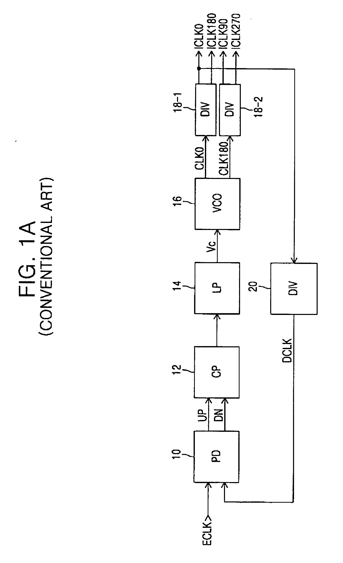
As a result, a problem with conventional phase lock loops is that when a power supply voltage is affected by noise, this noise may result in the output final clock signals ICLK0, ICLK180, ICLK90 and ICLK270 including error components.
In addition, conventional PLLs may have a disadvantage that they require a fairly long time until locking operation is complete

Method used


Image

  • Clock generation circuit and method of generating clock signals
  • Clock generation circuit and method of generating clock signals
  • Clock generation circuit and method of generating clock signals

Examples


Embodiment Construction

[0070] Various example embodiments of the present invention will now be described more fully with reference to the accompanying drawings in which some example embodiments of the invention are shown.

[0071] Detailed illustrative embodiments of the present invention are disclosed herein. However, specific structural and functional details disclosed herein are merely representative for purposes of describing example embodiments of the present invention. This invention may, however, be embodied in many alternate forms and should not be construed as limited to only the embodiments set forth herein.

[0072] Accordingly, while example embodiments of the invention are capable of various modifications and alternative forms, embodiments thereof are shown by way of example in the drawings and will herein be described in detail. It should be understood, however, that there is no intent to limit example embodiments of the invention to the particular forms disclosed, but on the contrary, example e...


PUM


Abstract

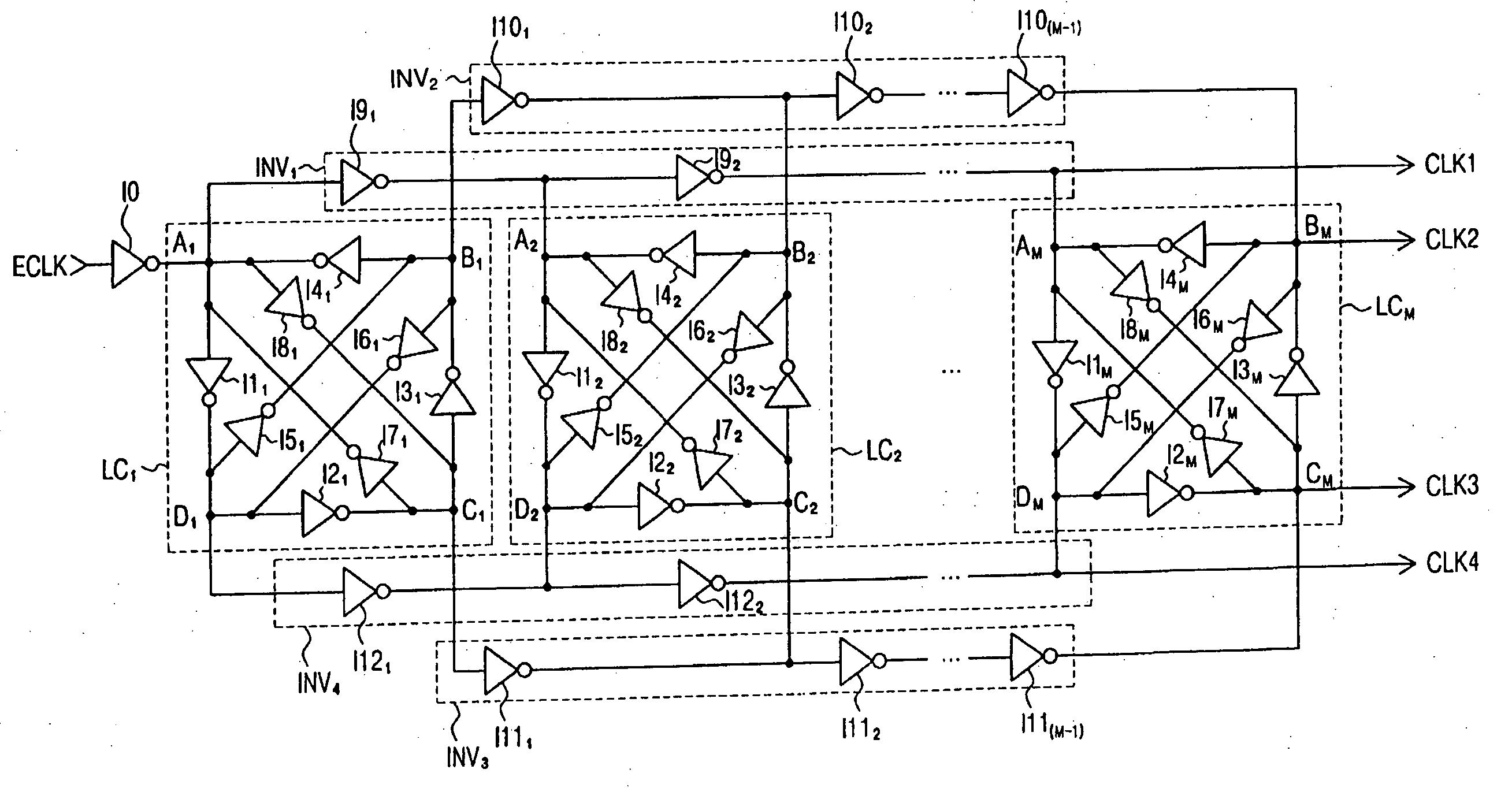
Clock generation circuit and method of generating clock signals. The clock generation circuit includes an inverter directly receiving an external clock signal and outputting an inverted external clock signal, M (where M is an integer ≧1) loop circuits arranged in series, the first loop circuit receiving the inverted external clock signal, each of the N loop circuits having n (where n is an integer ≧2) nodes, each of the M−1 loop circuits generating n intermediate internal clock signals, each at a corresponding one of the n nodes, wherein a frequency of the n intermediate internal clock signals is a multiple of a frequency of the external clock signal and the inverted external clock signal; and n sets of inverters, each including M−1 inverters connected in series, each of the M−1 inverters receiving a corresponding intermediate internal clock signal from a previous loop circuit and outputting a corresponding intermediate internal clock signal to a next loop circuit.

Description

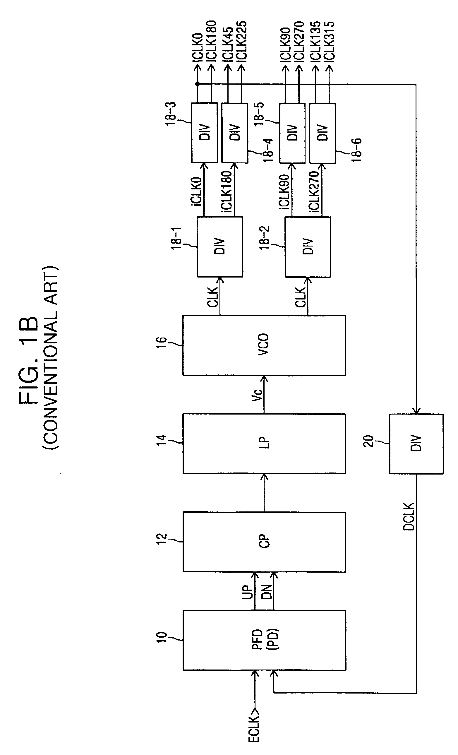
PRIORITY STATEMENT [0001] This U.S. non-provisional application claims priority under 35 U.S.C. § 119 to Korean Patent Application No. 2005-0101497, filed on Oct. 26, 2005, the entire contents of which are incorporated by reference. BACKGROUND OF THE INVENTION [0002]FIG. 1A illustrates a conventional phase locked loop, which may include a phase detector (PD) 10, a charge pump (CP) 12, a loop filter (LP) 14, a voltage controlled oscillator (VCO) 16, one or more dividers 18-1, 18-2, and / or one or more dividers 20. [0003] The phase detector (PD) 10 may receive an external clock signal ECLK and generate an UP or DN signal in response to a phase difference between the external clock signal ECLK and a feedback clock signal DCLK. When the phase of the external input signal ECLK leads that of the feedback clock signal DCLK, the UP signal is activated. When the phase of ECLK lags that of DCLK, the DN signal is activated. [0004] The charge pump (CP) 12 and / or the loop filter (LP) 14 may incre...

Claims


Application Information

Patent Timeline
IPC IPC(8): G06F1/04
CPCG06F1/04H03K5/1504H03K5/151H03K5/133H03L7/0814H03L7/0891H03L7/0812H03L7/0816H03L7/0818H03L7/08
Inventor KIM, KYU-HYOUN
Owner SAMSUNG ELECTRONICS CO LTD
Why Eureka
Try Eureka