
Transmission screen

a transmission screen and back projection technology, applied in the field of transmission screens, can solve the problems of difficult hurting the eyes, and difficult for those who observe the image to see the image, and achieve the effects of preventing the reduction of the sharpness of the projected image, reducing the difficulty of writing at a desired position, and improving the accuracy of writing

Inactive Publication Date: 2007-04-26
KIMOTO CO LTD
View PDF11 Cites 19 Cited by
  • Summary
  • Abstract
  • Description
  • Claims
  • Application Information

AI Technical Summary

Benefits of technology

[0023] Further, if the specular gloss of the writable and erasable surface (light emitting surface) is 70% or more, characters etc. written with a marker for white boards can be easily erased, and if the specular gloss is 135% or less, reflection of outer light and reduction in sharpness of images projected from a projector can be prevented. More preferably, if the specular gloss is 120% or less, the reduction in sharpness of the images can be further prevented, and adhered fingerprints can be made invisible.

Problems solved by technology

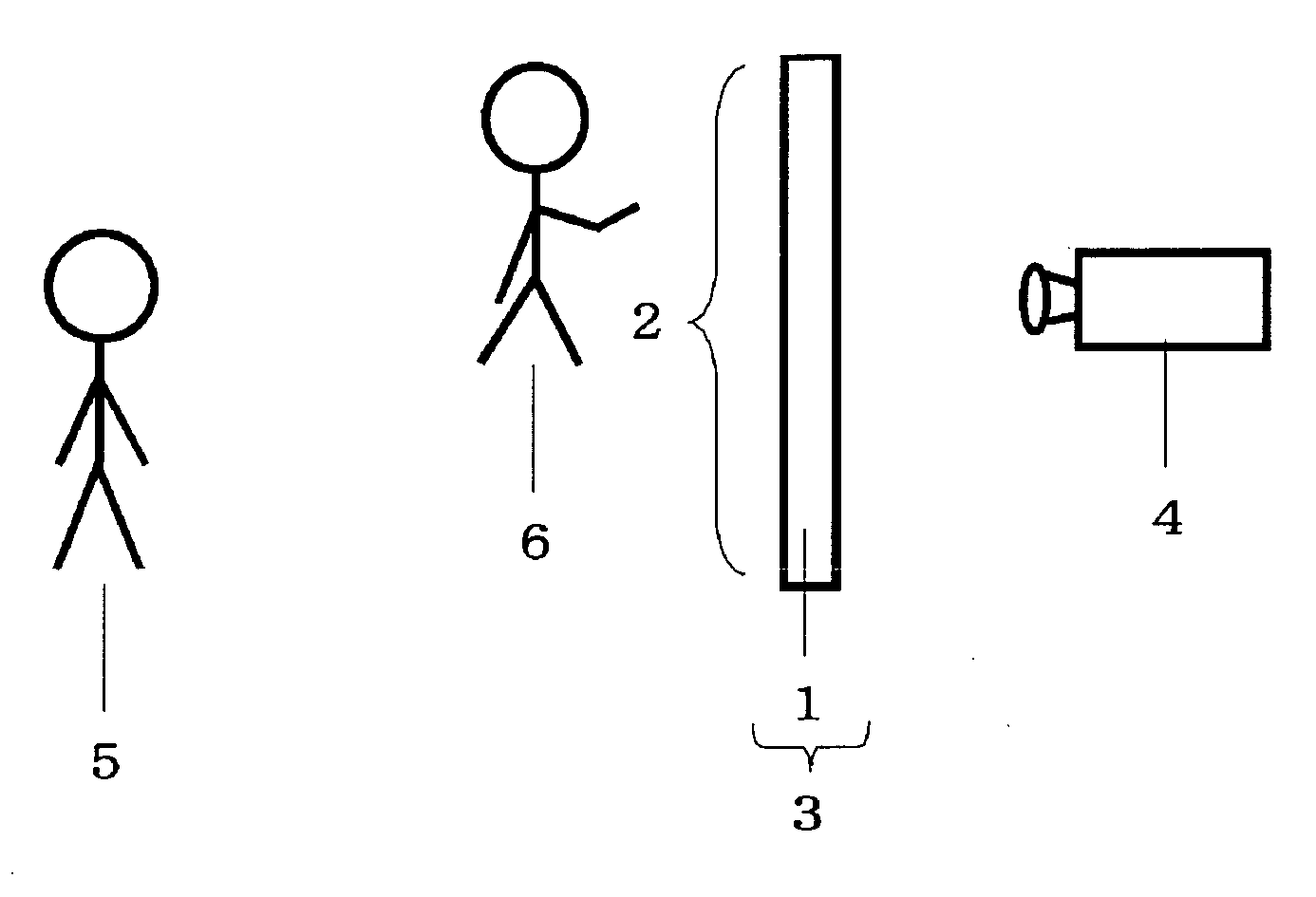
Therefore, when writing with a white board marker on an image projected on the screens is desired, writing at a desired position is difficult, because the light from the projector is interrupted by the body of the writer.
Moreover, reflection type screens have a problem that when a writer turns toward those who observe an image on a screen during writing on the screen, the light from a projector is directly irradiated on eyes of the writer and therefore hurt the eyes.
Furthermore, if the image from the projector is projected on the body or face of the writer, it is very hard for those who observe the image to see the image.
However, there are no conventional transmission screen taking writability for writing with a marker into consideration.
Even if writing with a marker is possible on such screens, the light emitting surfaces of the screens utilizing lenses suffer from bad erasability because of the uneven shape resulting from the shape of the lenticular lenses.
With a material using a light diffusing material, ink of a marker penetrates into the inside of the material, and therefore erasing is impossible.

Method used


Image

  • Transmission screen
  • Transmission screen
  • Transmission screen

Examples


example 1

[0087] Ingredient of the following composition was mixed and then subjected to a dispersion operation using a sand mill dispersion apparatus (Nano Mill, Asada Iron Works CO., LTD.) to prepare Light diffusing particle dispersion A.

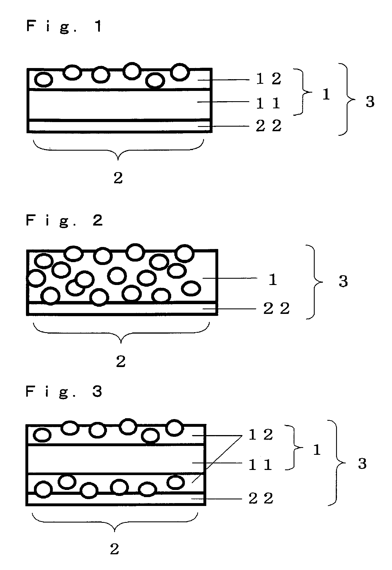
[0088] Then, on one surface of a 3-mm thick silicate glass plate as a substrate, Coating solution B for resin layer having the following composition was applied, dried and irradiated with an ultraviolet ray from a high-pressure mercury lamp to form a resin layer having a thickness of 6 μm. Then, on the other surface of this substrate, Coating solution C for light diffusing layer having the following composition was applied, dried and then cured at 60° C. for 24 hours to form a light diffusing layer having a thickness of 20 μm and thereby prepare a transmission screen of Example 1.

[0089] Ultraviolet curing type resin (acrylic resin, Diabeam UR6530, Mitsubishi Rayon Co., Ltd., solid content: 100%) 60.0 parts [0090] Matting agent (silica, Sylysia 446, Fuji S...

example 2

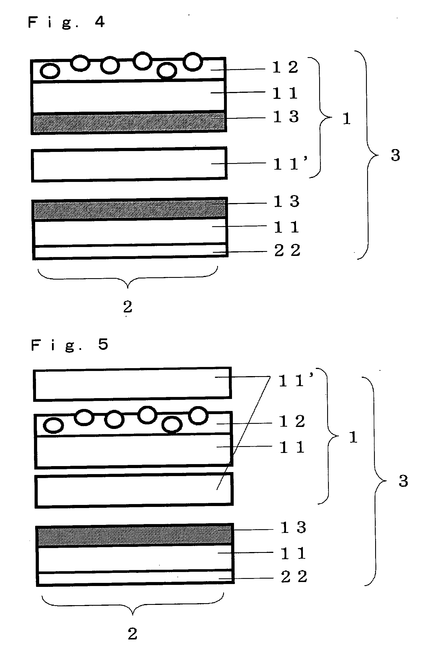
[0102] On one surface of a 100-μm thick transparent polyethylene terephthalate film (Lumilar T-60, Toray Industries, Inc.), a resin layer was formed in the same manner as in Example 1, and on the other surface, Coating solution D for adhesive layer having the following composition was applied and dried to form an adhesive layer having a thickness of 20 μm. The obtained laminate was adhered to one surface of the same silicate glass plate as that used in Example 1.

[0103] Then, on one surface of the same polyethylene terephthalate film as that used above, a light diffusing layer was formed in the same manner as in Example 1, and on the other surface, an adhesive layer was formed in the same manner as described above. This laminate was adhered to the other surface of the aforementioned silicate glass plate to prepare a transmission screen of Example 2.

[0104] Acrylic adhesive (Olibain BPS1109, TOYO INK MFG. CO., LTD., solid content: 40%) 100.0 parts [0105] Polyisocyanate (Olibain BHS85...

example 3

[0107] A transmission screen of Example 3 was prepared in the same manner as in Example 1 except that Coating solution E for resin layer, Light diffusing particle dispersion F and Coating solution G for light diffusing layer having the following compositions were used instead of Coating solution B for resin layer, Light diffusing particle dispersion A and Coating solution C for light diffusing layer used in Example 1, respectively, and a light diffusing layer having a thickness of 15 μm was formed.

[0108] Ultraviolet curing type resin (acrylic resin, Diabeam UR6530, Mitsubishi Rayon Co., Ltd., solid content: 100%) 60.0 parts [0109] Matting agent (silica, Sylysia 446, Fuji Silysia Chemical Ltd., mean particle size: 4.5 μm) 5.0 parts [0110] Pigment (silica, Aerosil R-972, NIPPON AEROSIL CO., LTD., mean particle size: 30 nm) 2.5 parts [0111] Photopolymerization initiator (Irgacure 651, Chiba Specialty Chemicals Co., Ltd.) 0.3 part [0112] Methyl ethyl ketone 80.0 parts [0113] Toluene 60...


PUM


Abstract

A transmission screen having a writable and erasable surface for one side is provided. This transmission screen is constructed so that the writable and erasable surface should have a specular gloss (JIS K5600-4-7:1999) of 70 to 135%, the transmission screen as a whole should have a haze (JIS K7136:2000) of 80% or more, and the surface opposite to the writable and erasable surface should have a specular gloss (JIS K5600-4-7:1999) of 10% or less. With this transmission screen, writing with a marker for white boards and erasing can be easily done while seeing images projected on the transmission screen, and the images from a projector do not become hard to see due to projection of the images on the body of a writer.

Description

TECHNICAL FIELD [0001] The present invention relates to a back projection type transmission screen with which an image projected from a projector can be observed from the side opposite to the projector through the screen. In particular, the present invention relates to a transmission screen with which writing with a marker for white boards and erasing are possible on an image projected from a projector. PRIOR ART [0002] Various boards having functions both of a screen on which an image is projected from a projector and a white board have conventionally been proposed and practically used in order to save spaces for installation and realize more efficient presentation (refer to Patent documents 1 and 2). [0003] However, these screens are reflection type screens for projection from a confronting position with which images projected from a projector are reflected by the screens and a reflected light is observed. Therefore, when writing with a white board marker on an image projected on ...

Claims


Application Information

Patent Timeline
IPC IPC(8): G09G5/00B43L1/10G03B21/10G03B21/56G03B21/62
CPCG03B21/62G03B21/625
Inventor NAKATA, HIROHIDEYANAGISAWA, RYOKOHARADA, MASAHIROMATSUSHITA, TAKESHISUGIYAMA, MAKOTO
Owner KIMOTO CO LTD
Learn More