Mobile galvanometer selective laser melting (SLM) forming device

A technology of laser melting and forming equipment, applied in the direction of improving process efficiency, improving energy efficiency, etc., can solve the problems of poor forming accuracy, difficult to increase forming size, deformation of light spot, etc., and achieve long life, high positioning accuracy, ability to strong effect

Active Publication Date: 2013-05-01
XIAN BRIGHT ADDTIVE TECH CO LTD
View PDF7 Cites 36 Cited by
  • Summary
  • Abstract
  • Description
  • Claims
  • Application Information

AI Technical Summary

Problems solved by technology

Due to the limitations of the mechanical structure and optical structure of the galvanometer, it is difficult to increase the size of the shape
The current galvanometer-type SLM equipment focuses the laser beam through the flat-field focusing lens, so the spot at the edge of the forming area is deformed, and the forming accuracy becomes poor.

Method used


Image

  • Mobile galvanometer selective laser melting (SLM) forming device

Examples


Embodiment Construction

[0024] The present invention will be further described below by specific embodiment:

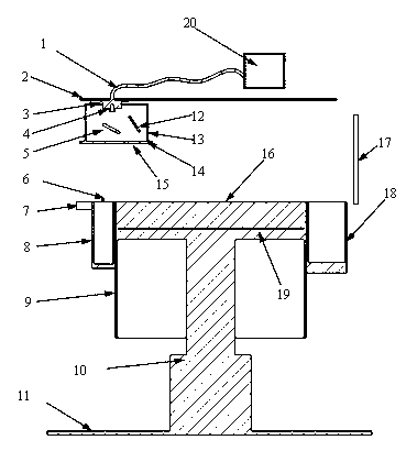
[0025] As shown in the accompanying drawings, the mobile galvanometer selective laser melting SLM forming equipment includes a numerical control system 15 connected with an X-axis linear motor 2 with a horizontal guide rail group and a Y-axis linear motor 3 with a longitudinal guide rail group through a communication line 1 , the communication line 1 is an optical fiber, the X-axis linear motor 2 and the Y-axis linear motor 3 constitute a scanning drive structure, and the scanning drive structure is drivingly connected with the laser beam expander and collimator mirror group 4, and the bottom of the laser beam expander collimator mirror group 4 Snap into the vibrating mirror unit, a forming working component is arranged under the vibrating mirror unit, and an inert gas curtain 17 is set between the forming working component and the vibrating mirror unit. The forming working assembly includes...


PUM


Abstract

A mobile galvanometer selective laser melting (SLM) forming device comprises a numerical-control system which is connected with an X-axis linear motor with a transverse lead rail group and a Y-axis linear motor with a longitudinal lead rail group through a communication circuit, the X-axis linear motor and the Y-axis linear motor form a scanning drive structure, the scanning drive structure is connected with a laser expanding collimation lens group in a drive way, a galvanometer unit is clamped into the bottom of the laser expanding collimation lens group, a forming working assembly is arranged below the galvanometer unit, and an inert gas curtain is arranged between the forming working assembly and the galvanometer unit. Due to the adoption of the mobile galvanometer SLM forming device, the defects that spots are formed on the edge of a forming area, the forming precision is poor and the size of a formed piece is easy to increase can be avoided.

Description

technical field [0001] The invention relates to the technical field of rapid prototyping, in particular to a mobile vibrating mirror selective laser melting SLM forming equipment. Background technique [0002] Selective laser melting SLM is a method of direct forming of metal parts and is the latest development of rapid prototyping technology. This technology is based on the most basic idea of ​​rapid prototyping, that is, the "incremental" manufacturing method of layer-by-layer cladding, and directly forms parts with specific geometric shapes according to the three-dimensional CAD model. During the forming process, the metal powder is completely melted to produce metallurgical bonding. Metal parts with complex shapes and structures that cannot be manufactured by traditional machining methods are one of the main directions for the application of laser rapid prototyping technology. Has the following advantages: [0003] (1) It can be directly made into terminal metal produc...

Claims


Application Information

Patent Timeline
Patent Type & Authority Applications(China)
IPC IPC(8): B22F3/105
CPCY02P10/295Y02P10/25
Inventor 黄卫东薛蕾杨东辉赵晓明
Owner XIAN BRIGHT ADDTIVE TECH CO LTD
Why Eureka
Try Eureka