Optical information verifying device

a technology of optical information and verification device, which is applied in the direction of measurement device, sensing by electromagnetic radiation, instruments, etc., can solve the problems of deterioration of printing quality, consumer inability to reach the homepage, and damage to the corporate image of the advertiser, and achieve the effect of recording quite readily optical information and high quality

Inactive Publication Date: 2007-04-26
DENSO WAVE INC
View PDF1 Cites 13 Cited by
  • Summary
  • Abstract
  • Description
  • Claims
  • Application Information

AI Technical Summary

Benefits of technology

[0017] According to the present invention, when a record state of the optical information is detected to be improper, an improving point indicating in which respect and in what way the recorded optical information should be corrected is provided. This makes it possible to record quite readily the optical information in high quality without asking advice from an expert.

Problems solved by technology

In addition, deterioration takes place on the printing quality depending on environmental change after a product has arrived on the market.
Such deterioration in the printing quality of optical information not only affects management of products attached with the optical information, but also causes a problem that when the optical information is used as information medium to direct a consumer to a relevant homepage as mentioned above, the consumer cannot reach the homepage, and in addition, a corporate image of the advertiser may be harmed due to unreadable information on the products.
Accordingly, when an evaluation result indicates that printed condition is not good, it does not show any definite solution on which part of the two-dimensional code printed should be corrected, and which points should be improved to enable optical information to be properly printed.
However, this requires high cost and time consuming process.
Therefore, also in this case, considerable increase in cost and time is unavoidable to correctly extract the improving points.

Method used


Image

  • Optical information verifying device
  • Optical information verifying device
  • Optical information verifying device

Examples


Embodiment Construction

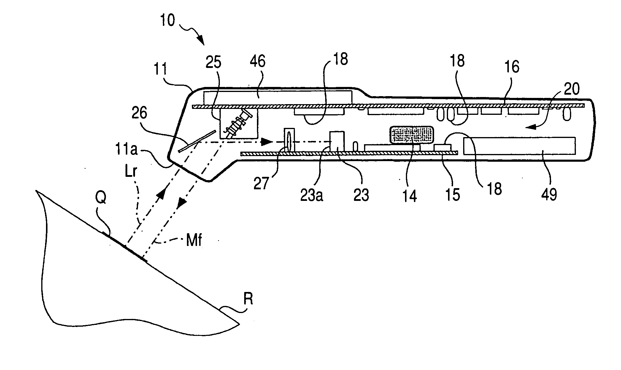
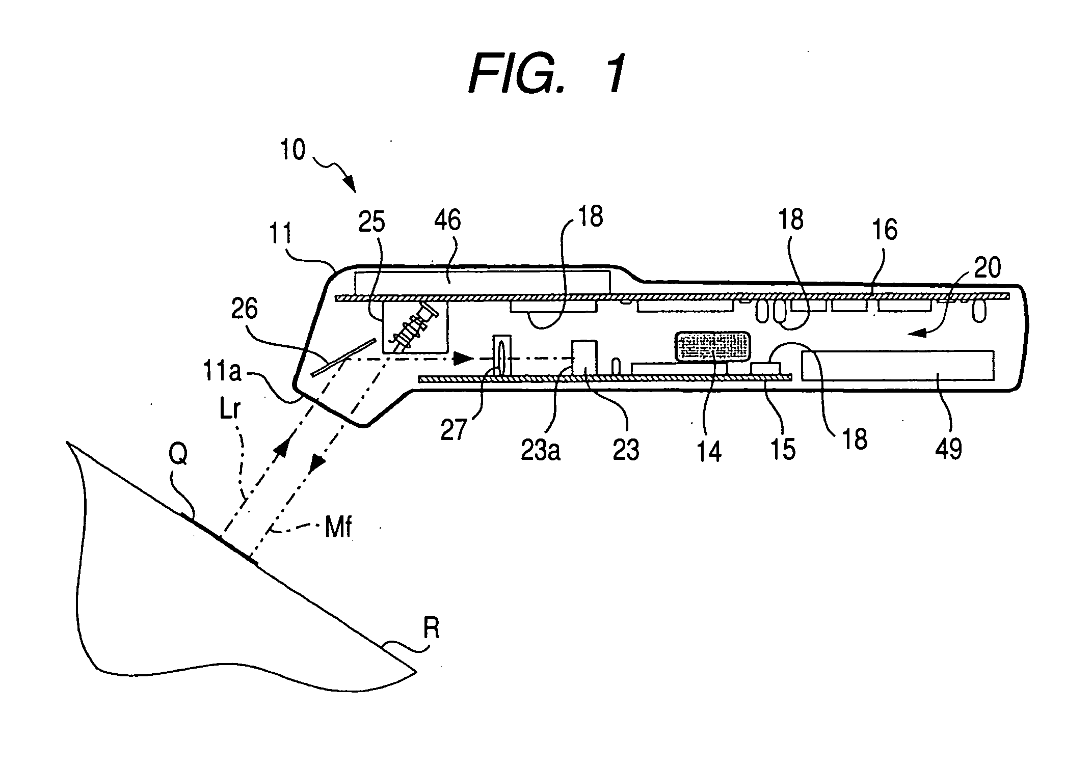
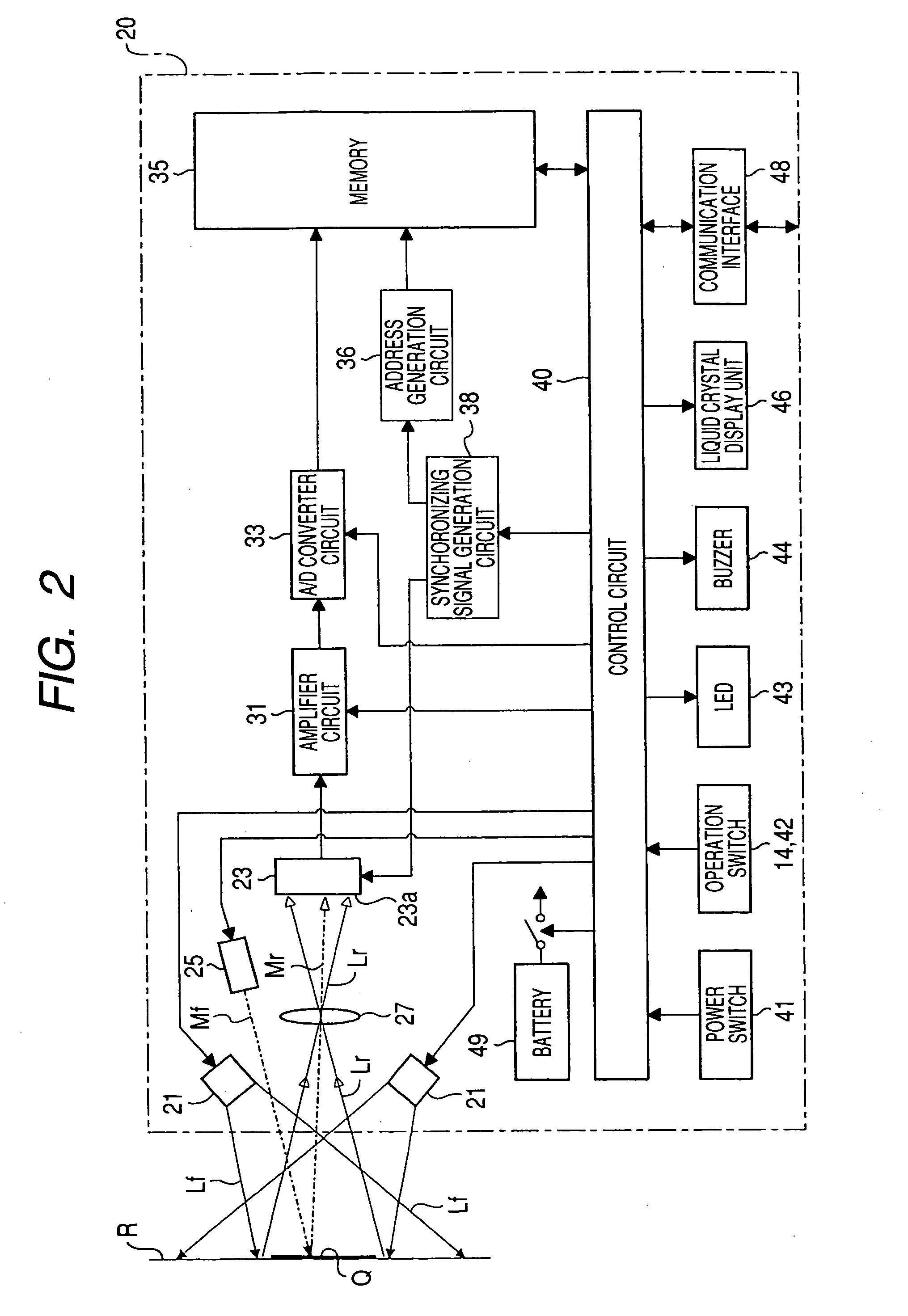
[0049] Hereunder, an optical information verification device of an embodiment according to the present invention is described below in detail with reference to the accompanying drawings. First, a two-dimensional code verifier 10 of the present embodiment is described with reference to FIGS. 1 to 3.

[0050] As shown in FIG. 1, the two-dimensional code verifier 10 mainly comprises an elongated housing 11 formed in a substantially rectangular box-like configuration, a circuit section 20 accommodated inside the housing 11, and a battery 49 received in the housing 11 to supply driving electric power to the circuit section 20.

[0051] The housing 11, made of, for instance, a molded component part formed of synthetic resin such as ABS resin, has one end formed with a readout port 11a with a “bent neck shape” leaning forward toward a backside direction of the housing 11. The readout port 11a has an opening portion, available to guide an incident light beam to a light-receiving sensor 23 of th...


PUM


Abstract

The optical information verification apparatus includes an image pickup section picking up an image of optical information recorded on a display medium, a measuring section measuring a record state of optical information picked up by the image pickup device in terms of a given evaluation item and outputting a measured value of the record state, a comparing section comparing the measured value output from the measuring section with a given reference value, and outputting a comparison result, and an improving point outputting section converting the comparison result output from the comparing section into an improving point associated with the comparison result, and outputting the improving point.

Description

CROSS-REFERENCE TO RELATED APPLICATION [0001] This application is related to Japanese Patent Application No. 2005-311265 filed on Oct. 26, 2005, the contents of which are hereby incorporated by reference. BACKGROUND OF THE INVENTION [0002] 1. Technical Field of the Invention [0003] The present invention relates to an optical information verifying device configured to measure record condition of optical information recorded or printed on display media in terms of given evaluation items, compare a measured value with a given reference value, and evaluate the record condition of the optical information on the basis of the comparison result. [0004] 2. Description of the Related Art [0005] Optical information, such as bar codes and two-dimensional codes printed on display media such as product labels or films attached onto industrial products or the like have been used for distribution managements. Currently, however, optical information is being used in advertisements on newspapers or m...

Claims


Application Information

Patent Timeline
Patent Type & Authority Applications(United States)
IPC IPC(8): G01B11/24
CPCG06K7/14
Inventor TANO, ATSUSHI
Owner DENSO WAVE INC
Why Eureka
Try Eureka