Embedded information carrier for optical data

a technology of optical data and information carrier, applied in the field of holographic, diffractive and optically variable security features, can solve the problems of increasing the level of security, increasing the cost and effort of those trying to create forgeries or counterfeit items, and compromising the present use of holographic seals as security features, etc., and achieves the effect of not cost-effective reproduction

Inactive Publication Date: 2007-04-26
ERICKSON RONALD R +2
View PDF10 Cites 0 Cited by
  • Summary
  • Abstract
  • Description
  • Claims
  • Application Information

AI Technical Summary

Benefits of technology

[0009] The present invention solves the problems associated with the prior art security features by adding additional levels of security and / or new security features that are extremely difficult, expensive and are not cost effective to reproduce by a forger or counterfeiter.
[0014] The security holograms according to the present invention may include multi-depth information. This includes different groups of information that are projected in different three-dimensional planes and / or different groups of information that are read from different locations. A coded password could be designed into the security hologram with different pieces of the code included in different planes as projected by the security hologram and / or readable from different locations with respect to the position of the security hologram. The division of the coded password into different planes allows the password to be incorporated into a matrix, which adds significantly more levels of complexity and makes it much more difficult to forge or counterfeit. The coded password may be comprised of a single type of information or various types of information. For example, the information may be coded using, for example, binary data, reflective wavelength, reflectance strength, reflection angle, or any combination thereof.
[0025] The security hologram may incorporate varying reflection angles into the digit locations. Each digit location could incorporates a predetermined reflection angle such that each bit of the unique code would be reflected at a particular angle to be read by a particular detector. Each digit location of the unique code would be able to represent more than binary ones and zeros, but can represent any number of digits depending on the number of detectors used. For example, if five detectors are used, either none or any one of the five detectors can detect a digit upon illumination of the digit locations. The five detectors, for example, may each be located at a particular position with respect to the security hologram. Upon illumination, each individual digit location would be reflected to a particular location to be detected by a detector in the corresponding position, thereby providing for a greater number of unique codes utilizing fewer digit locations. An eight digit code incorporated into the security hologram would contain six times as much information as a binary eight digit code utilizing a single detector with no angular differentiation. Such a security hologram is much more difficult to reproduce due to the specific and defined reflection angles required for the digits in the security hologram to allow for an accurate reading of the code.

Problems solved by technology

Because of the relative difficulty in the past of producing these types of holographic seals and optical security features, this added feature provided an increased level of security and added significant cost and effort for those trying to create forgeries or counterfeit items.
The present use of holographic seals as a security feature has been compromised by these new fabrication technologies, and some of the forgery holograms are even of a superior quality as compared to the legitimate item that is being manufactured and used for security purposes.
Similarly, as a result of the availability of these fabrication technologies, the embedded hologram feature on the new U.S. currency has been compromised leading to the successful forgery of such currency.

Method used


Image

  • Embedded information carrier for optical data
  • Embedded information carrier for optical data
  • Embedded information carrier for optical data

Examples


Embodiment Construction

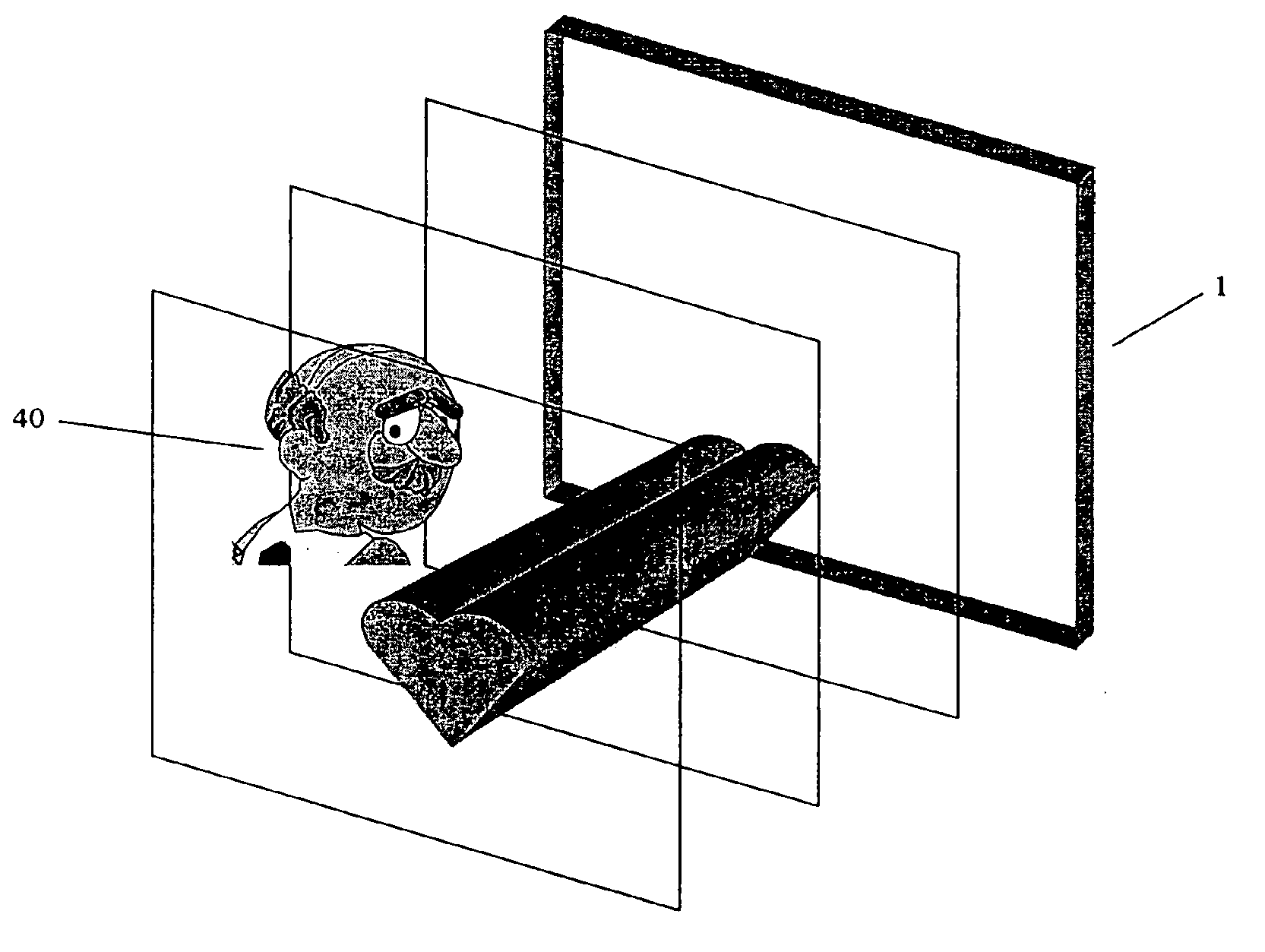
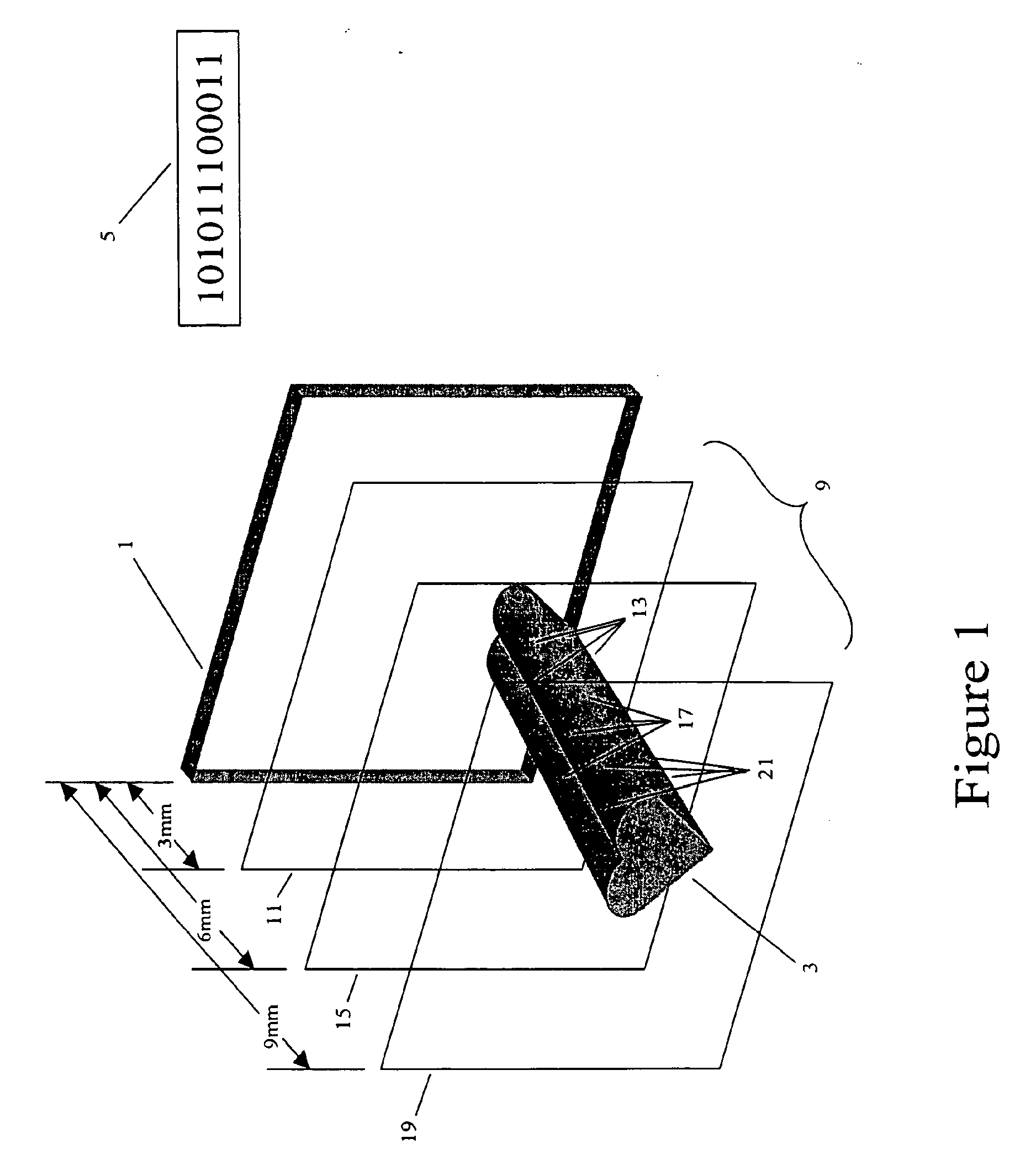
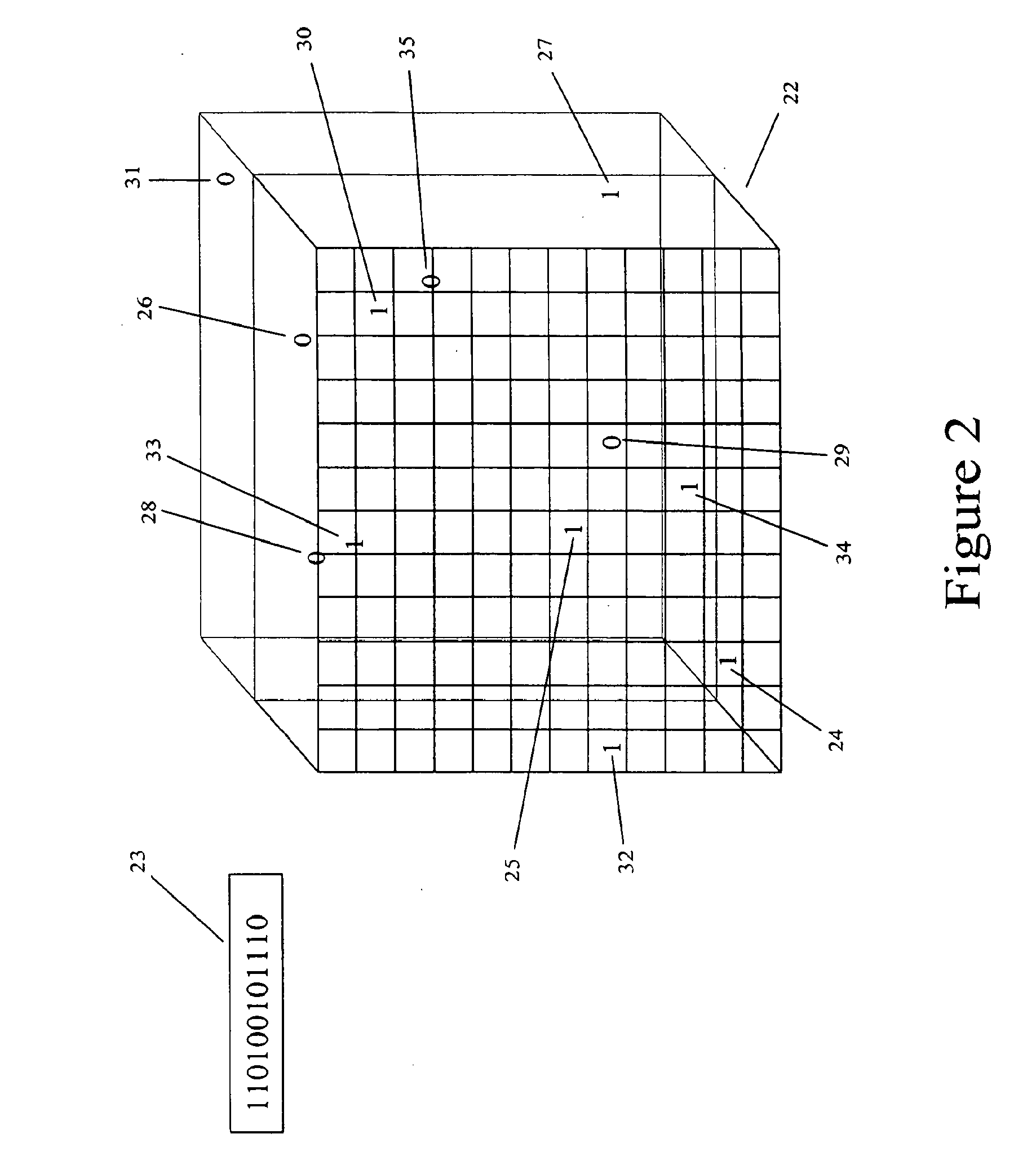
[0053] As shown in FIG. 1, the security hologram 1 includes information that when viewed or read for verification purposes, is presented as a three-dimensional image 3. The image 3 includes coded information 5 in a predetermined pattern. This coded information 5 is arranged in a predetermined pattern that will allow for varying levels of security. The predetermined pattern of the coded information 5 is arranged as a three-dimensional matrix 9. The three-dimensional matrix 9 includes information encompassing three discrete planes each located at a predetermined distance from the plane of the security hologram 1. The first plane 11 of the three-dimensional matrix 9 is located at approximately three millimeters from the surface of the security hologram 1. This first plane 11 includes only a first portion 13 of the coded information 5 stored in the security hologram 1 and alone is insufficient to establish a successful confirmation of security clearance identity verification. The second...


PUM

PropertyMeasurementUnit
angleaaaaaaaaaa
optical informationaaaaaaaaaa
distanceaaaaaaaaaa

Abstract

In a system for authenticating information, a holographic element, including a first layer of optical information in a first coded pattern and a second layer of optical information in a second coded pattern is inserted into a reader. The reader includes an opening into which the holographic element may be positioned, a light source, a first detector positioned at a first predetermined distance from the location of the holographic element when the holographic element is positioned in the opening, and a second detector positioned at a second predetermined distance from the location of the holographic element when the holographic element is positioned in the opening.

Description

CLAIM TO PRIORITY [0001] This application claims priority from U.S. patent application Ser. No. 10 / 822,044, filed on Apr. 9, 2004, and U.S. Patent Application Ser. No. 60 / 462,566, filed on Apr. 10, 2003.FIELD OF THE INVENTION [0002] The present invention relates to holographic, diffractive and optically variable security features, methods for creating such security features, and apparatus, systems, and methods for verification of such security features. More specifically, the present invention relates to optically variable security features having embedded therein optical security information, including multi-layer and multi-wavelength security information, methods for manufacturing such security features having embedded optical security information, and devices, systems, and methods for reading or verification of the embedded optical security information in such security features. The present invention also relates to security features that are non-removable or self-destructing upo...

Claims


Application Information

Patent Timeline
Patent Type & Authority Applications(United States)
IPC IPC(8): G02B5/32G03H1/22G11B7/0065G11B23/28
CPCB42D2035/14B42D25/328G03H1/0011G03H1/22G03H2001/0413G03H2001/0497G03H2001/184G03H2001/2231G03H2001/2244G03H2210/33G03H2210/53G03H2270/31G11B23/283G03H1/2249G03H2210/30Y10S428/916G02B5/32
Inventor ERICKSON, RONALD R.BOCK, JOEL N.SANDLER, ELIEZER D.
Owner ERICKSON RONALD R
Why Eureka
Try Eureka