
Method for manufacturing cemented lens, cemented lens and projector apparatus

Inactive Publication Date: 2007-04-26
FUJI PHOTO OPTICAL CO LTD
View PDF4 Cites 14 Cited by
  • Summary
  • Abstract
  • Description
  • Claims
  • Application Information

AI Technical Summary

Benefits of technology

[0018] According to the above configurations, at least two lenses one of which has a concave surface and the other of which has a convex surface are cemented through the concave surface and the convex surface as cementing surfaces. In this event, the lenses are bonded by adhesive applied to a circumferential end portion located out of an effective area serving as a chief optical path of each lens. Thus, there is no fear that light passes through a bonding layer formed between two lenses as in a background-art cemented lens. It is therefore unnecessary to take into consideration the deterioration of optical performance of adhesive in a cemented lens when an optical system using the cemented lens is designed. The degree of freedom in selecting the layout position of the cemented lens can be increased.

Problems solved by technology

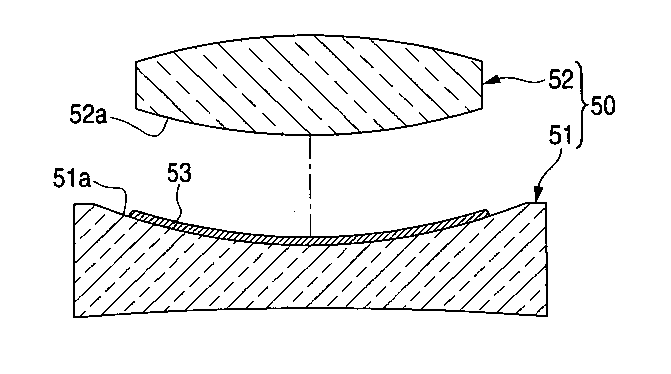
However, there is a problem that the cemented lens 50 of the related art cannot be used in a place exposed to intensive light, for example, in a place close to an exit pupil of a projection lens for the project or apparatus.
Therefore, the energy of light per unit area becomes so high that there arises a problem particularly.
Thus, it is difficult to use the cemented lens 50 in a site exposed to intensive light, and the degree of freedom in designing the optical system is restricted.
It is therefore unnecessary to take into consideration the deterioration of optical performance of adhesive in a cemented lens when an optical system using the cemented lens is designed.

Method used


Image

  • Method for manufacturing cemented lens, cemented lens and projector apparatus
  • Method for manufacturing cemented lens, cemented lens and projector apparatus
  • Method for manufacturing cemented lens, cemented lens and projector apparatus

Examples


Embodiment Construction

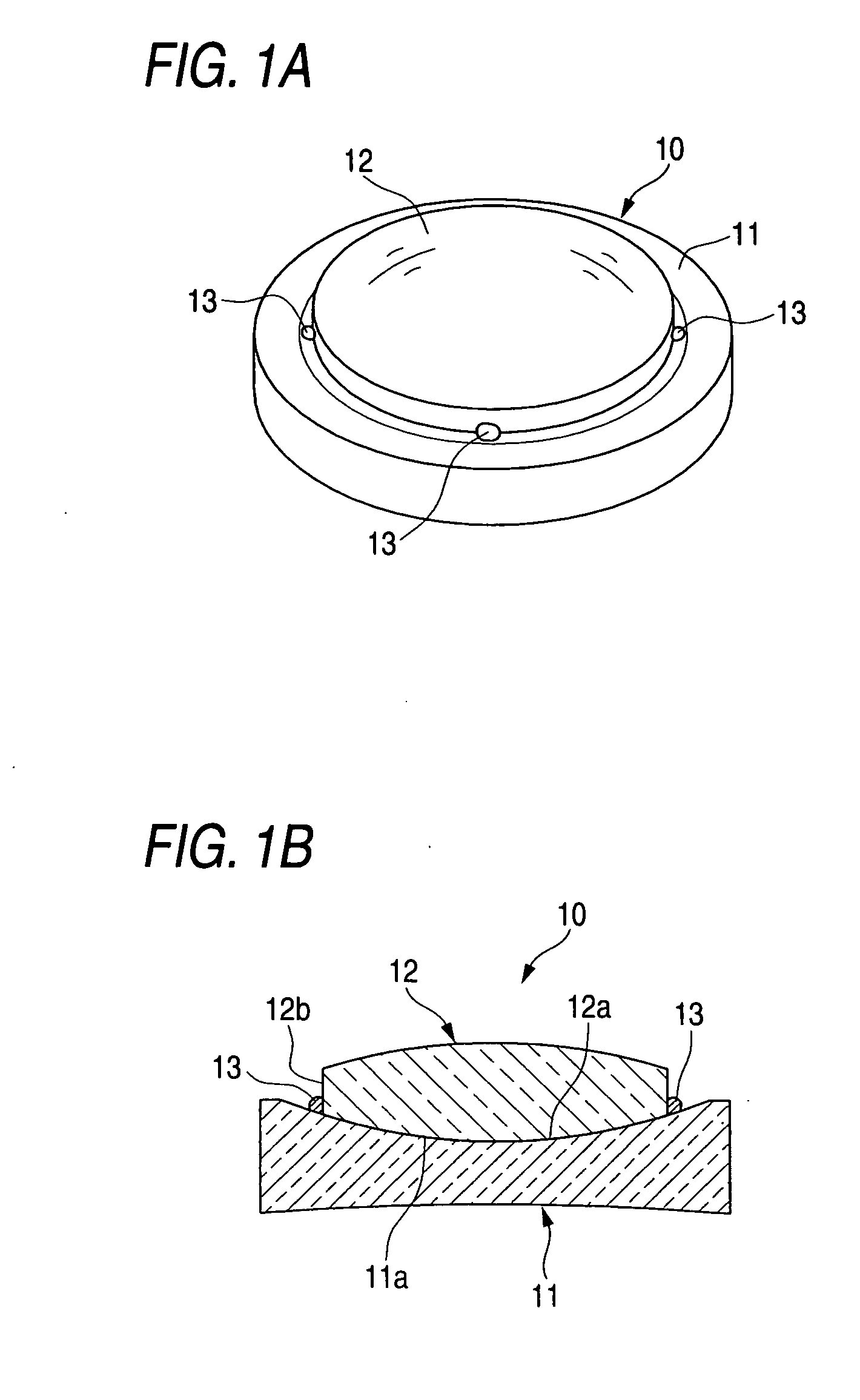
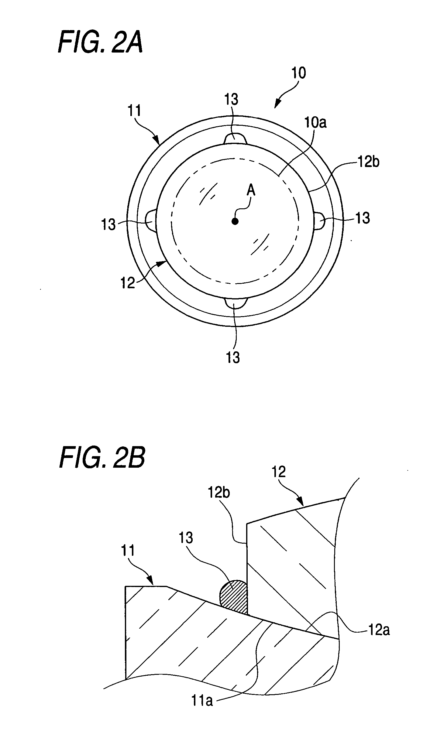
[0027] A cemented lens 10 shown in FIGS. 1A and 1B includes two lenses, i.e. a first lens 11 having a concave surface 11a and a second lens 12 having a convex surface 12a. For example, the first lens 11 is a concave lens having a negative refracting power, and the second lens 12 is a convex lens having a positive refracting power. The concave surface 11a of the first lens 11 and the convex surface 12a of the second lens 12 have one and the same curvature. The first lens 11 and the second lens 12 are cemented through the concave surface 11a and the convex surface 12a as cementing surfaces. As shown in FIGS. 2A and 2B, the first lens 11 and the second lens 12 are bonded by adhesive 13 in a circumferential end portion located out of their effective area 10a.

[0028] The effective area 10a is a chief area which will serve as a chief optical path including an optical axis A of the cemented lens 10, and which includes the centers of the lens surfaces of the lenses 11 and 12 including the c...


PUM


Abstract

A cemented lens is produced by cementing a first lens having a concave surface with a second lens having a convex surface. The second lens is placed on the concave surface of the first lens to align the concave surface with the convex surface. Adhesive is dropped in each predetermined place around the second lens by a predetermined quantity to abut against an outer circumferential end of the second lens. The position of the second lens is adjusted. The adhesive is irradiated with ultraviolet light. Thus, the outer circumferential end of the second lens is bonded with the concave surface of the first lens. There is no bonding layer between the cementing surfaces as in the related art. There is no fear that light passes through the bonding layer. It is therefore unnecessary to consider deterioration of optical performance caused by deformation of the adhesive exposed to intensive light.

Description

BACKGROUND OF THE INVENTION [0001] 1. Technical Field [0002] The invention relates to a cemented lens including at least two lenses cemented through cementing surfaces one of which is a concave surface of one of the lenses and the other of which is a convex surface of the other of the lenses, a method for manufacturing the cemented lens, and a projector apparatus using the cemented lens. [0003] 2. Description of the Related Art [0004] As shown in FIGS. 8A and 8B, there has been known a cemented lens 50 composed of two lenses, that is, a first lens 51 and a second lens 52 cemented through cementing surfaces. One of the cementing surfaces is a concave surface 51a of the first lens 51. The other of the cementing surfaces is a convex surface 52a of the second lens 52. The cemented lens 50 configured thus is, for example, used as a lens for correcting chromatic aberration in an optical system of a projector apparatus etc. for projecting image light on a screen to thereby display an image...

Claims


Application Information

Patent Timeline
IPC IPC(8): G02B9/00
CPCB29D11/0073G02B7/025
Inventor SHIMIZU, HITOSHI
Owner FUJI PHOTO OPTICAL CO LTD
Learn More