
CPP-GMR magnetic head having GMR-screen layer

Inactive Publication Date: 2007-04-26
WESTERN DIGITAL TECH INC
View PDF18 Cites 18 Cited by
  • Summary
  • Abstract
  • Description
  • Claims
  • Application Information

AI Technical Summary

Benefits of technology

[0006] It is a feature of the present invention to provide a confined-current-path type CPP-GMR which can achieve stably a high magnetoresistance and a high output.
[0015] According to the present invention, high magnetoresistance and high output can be achieved by applying a structure using a GMR-screen layer, in which a current-path-confinement effect and a GMR effect appear at the same time in a CPP magnetoresistive layered film. In a magnetic recording / reproducing apparatus in which this is used for a read head, high recording density can be achieved, that is, a short recording wavelength while recording in a recording medium and recording with a narrow recording track width can be achieved, therefore, a sufficient output can be obtained and it is possible to keep the recording excellent.

Problems solved by technology

A disadvantage of a magnetic head using a conventional magnetoresistive magnetic sensor is that it cannot achieve high output.
Specifically, a problem in the technology of a so-called confined-current-path type CPP-GMR is that it cannot control the fabrication of a fine pin-hole structure for partially flowing current in the film thickness direction.
Therefore, in a conventional technology, it is impossible to improve the output of a confined-current-path type CPP-GMR.

Method used


Image

  • CPP-GMR magnetic head having GMR-screen layer
  • CPP-GMR magnetic head having GMR-screen layer
  • CPP-GMR magnetic head having GMR-screen layer

Examples


embodiment 1

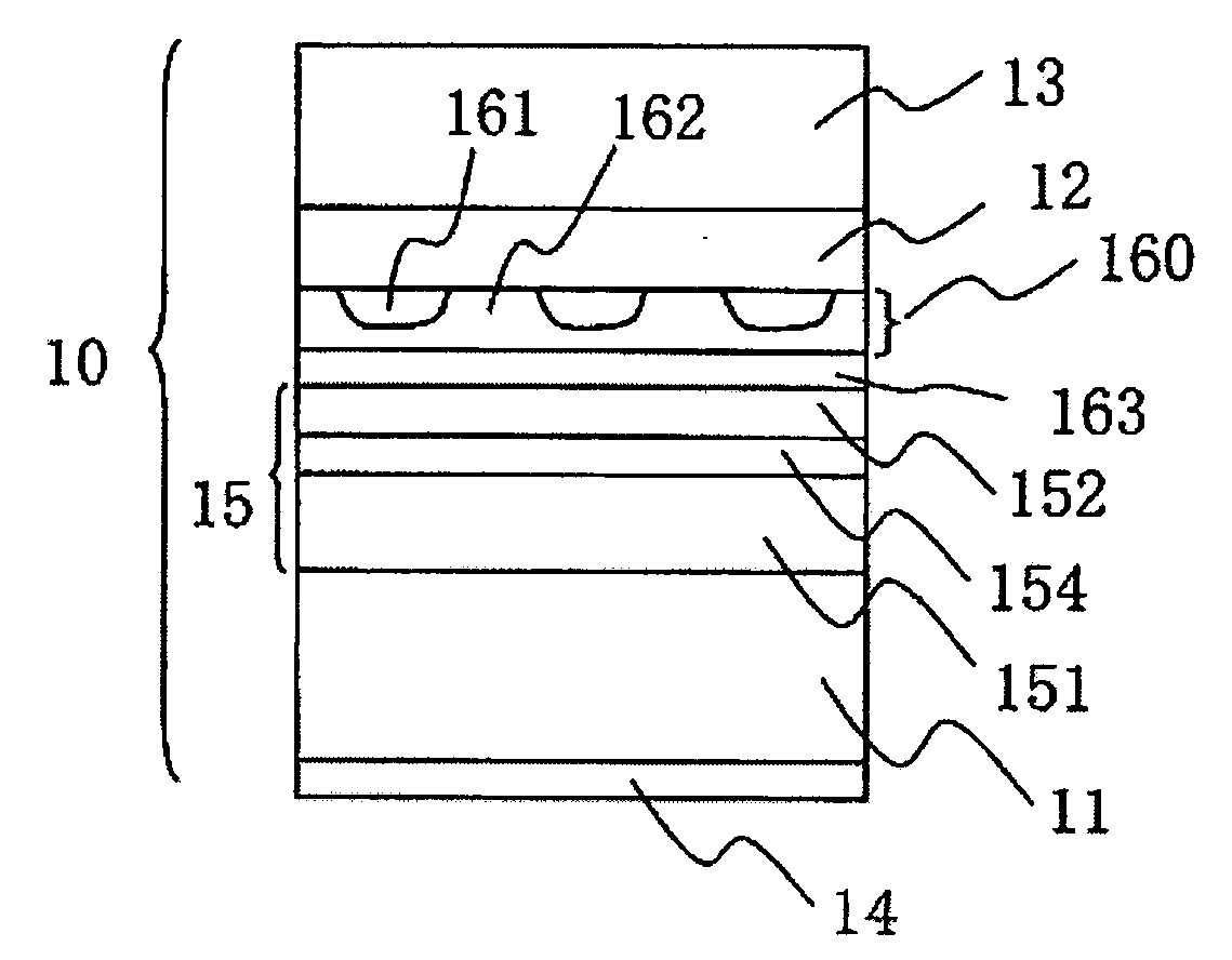
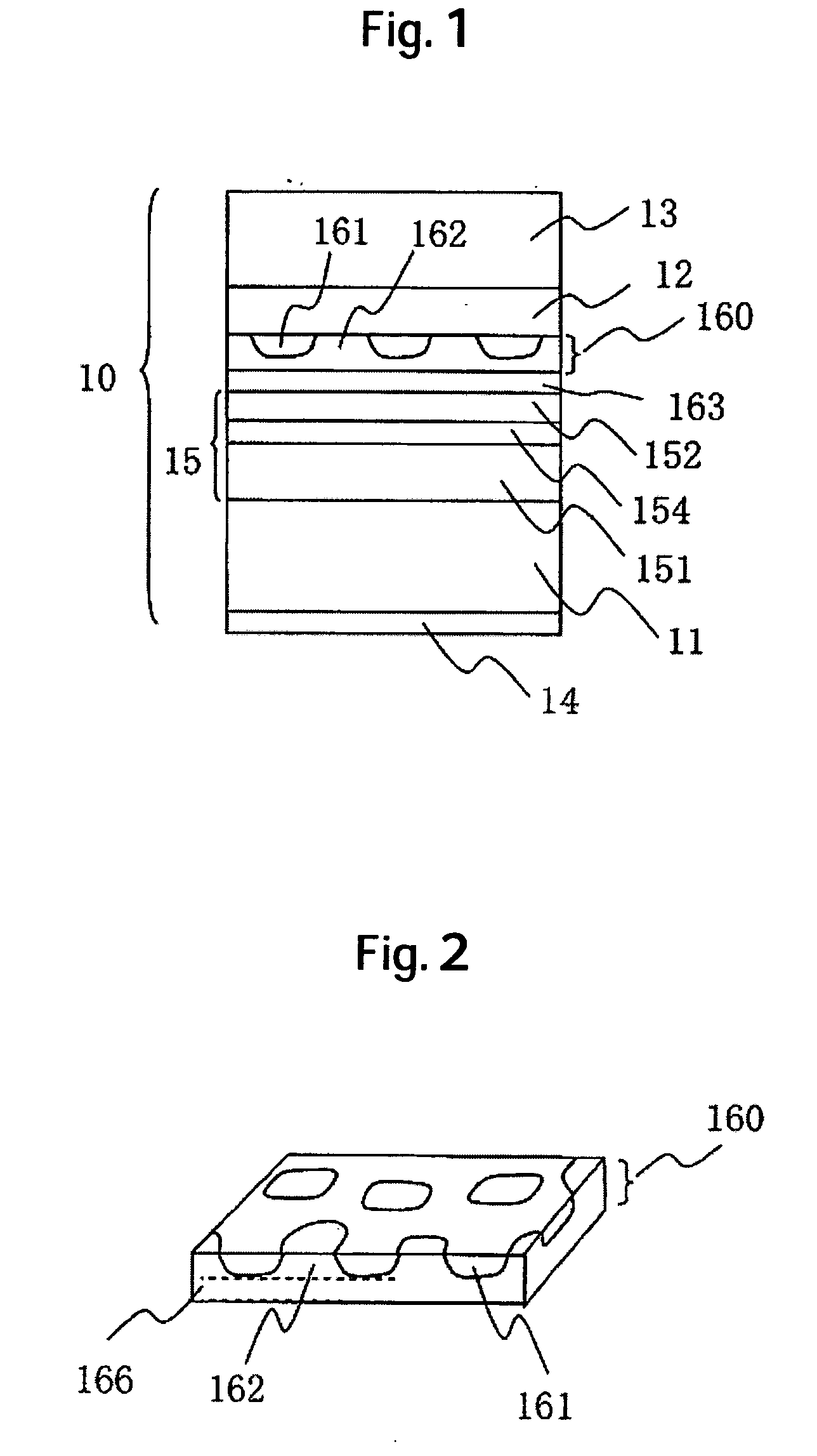
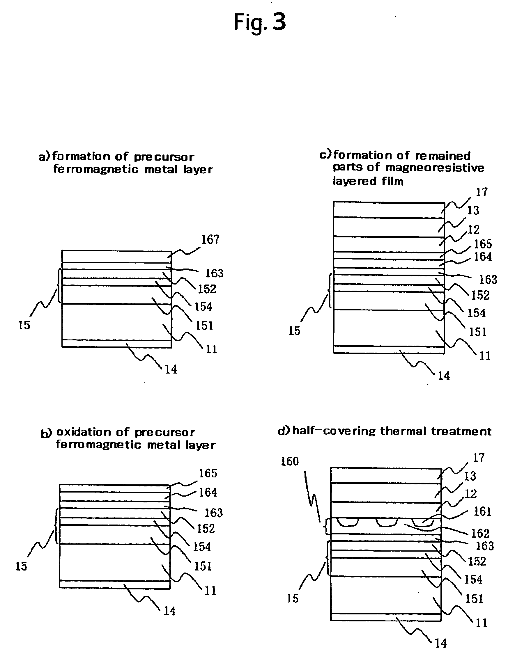
[0040]FIG. 1 is a layered structure of a typical magnetoresistive read sensor of the present invention. A magnetoresistive layered film 10 is formed by stacking a soft magnetic free layer 13 and a GMR-screen layer 160 through a non-magnetic intermediate layer 12. The GMR-screen layer 160 has a spike-like ferromagnetic metal 162 and the spike-like ferromagnetic metal 162 is exposed or sticks out from the partial holes existing in an oxide layer 161. That is, the oxide layer 161 with holes covers a ferromagnetic metal layer underneath it, a part of the ferromagnetic metal layer fills in the hole parts of the oxide layer in a convex shape, is exposed and contacts the adjacent non-magnetic intermediate layer through the hole parts. According to this structure, the GMR screen layer 160 satisfies both the current-path-confinement effect, which limits the current-flow path of the current flowing in the film thickness direction, and, at the same time, the function for the spin-dependent sca...


PUM


Abstract

A spin-valve type magnetic head which has sufficiently high output is provided. In one embodiment, a structure in which high output coexists with high stability is achieved by letting a GMR-effect and a current-path-confinement effect manifest themselves at the same time in a GMR-screen layer consisting of a ferromagnetic metal spike-like part and a half-covering oxide layer.

Description

CROSS-REFERENCES TO RELATED APPLICATIONS [0001] This application claims priority from Japanese Patent Application No. JP2005-306251, filed Oct. 20, 2005, the entire disclosure of which is incorporated herein by reference. BACKGROUND OF THE INVENTION [0002] The present invention relates to a magnetic recording / reproducing apparatus and a magnetic head equipped therein, and specifically, relates to a magnetic head for a high density magnetic recording / reproducing apparatus and a manufacturing method thereof. [0003] A magnetoresistive magnetic head is used for a read sensor in a high density magnetic recording technology mainly composed of a hard disk and is a part which exerts a strong influence on the performance of the magnetic recording technology. Within the framework where the recording density of magnetic recording apparatus was made higher rapidly, the prior art could not achieve a magnetic recording apparatus with a sufficiently high recording density; specifically a magnetore...

Claims


Application Information

Patent Timeline
IPC IPC(8): G11B5/127G11B5/33
CPCB82Y10/00B82Y25/00G11B5/3929G11B2005/3996
Inventor HOSHIYA, HIROYUKIHOSHINO, KATSUMIMEGURO, KENICHISATO, YOKATADA, HIROYUKI
Owner WESTERN DIGITAL TECH INC
Learn More