Pneumatic bioreactor

a bioreactor and pneumatic technology, applied in the field of pneumatically operated mixers, can solve the problems of inability to achieve large-scale, expensive operating machinery, and inability to provide efficient mixing for large-scale (greater than 1000 liters) , to achieve the effect of efficient and thorough mixing solutions, accurate control, and large volum

Inactive Publication Date: 2007-04-26
PBS BIOTECH INC
View PDF65 Cites 41 Cited by
  • Summary
  • Abstract
  • Description
  • Claims
  • Application Information

AI Technical Summary

Benefits of technology

[0011] It is an objective of the present invention to provide a pneumatic bioreactor that is capable of efficiently and thoroughly mixing solutions without contamination. It is a further objective to such a reactor that can be scaled to relatively large sizes using the same technology. It is a still further objective of the invention to a bioreactor that can be produced in a disposable form

Problems solved by technology

The procedure of cleaning and sterilization requires a significant amount of time and resources, especially, to monitor and to validate each cleaning step prior to reuse for production of biopharmaceutical products.
While several mixing methods of liquid in disposable bioreactors have

Method used


Image

  • Pneumatic bioreactor
  • Pneumatic bioreactor
  • Pneumatic bioreactor

Examples


Embodiment Construction

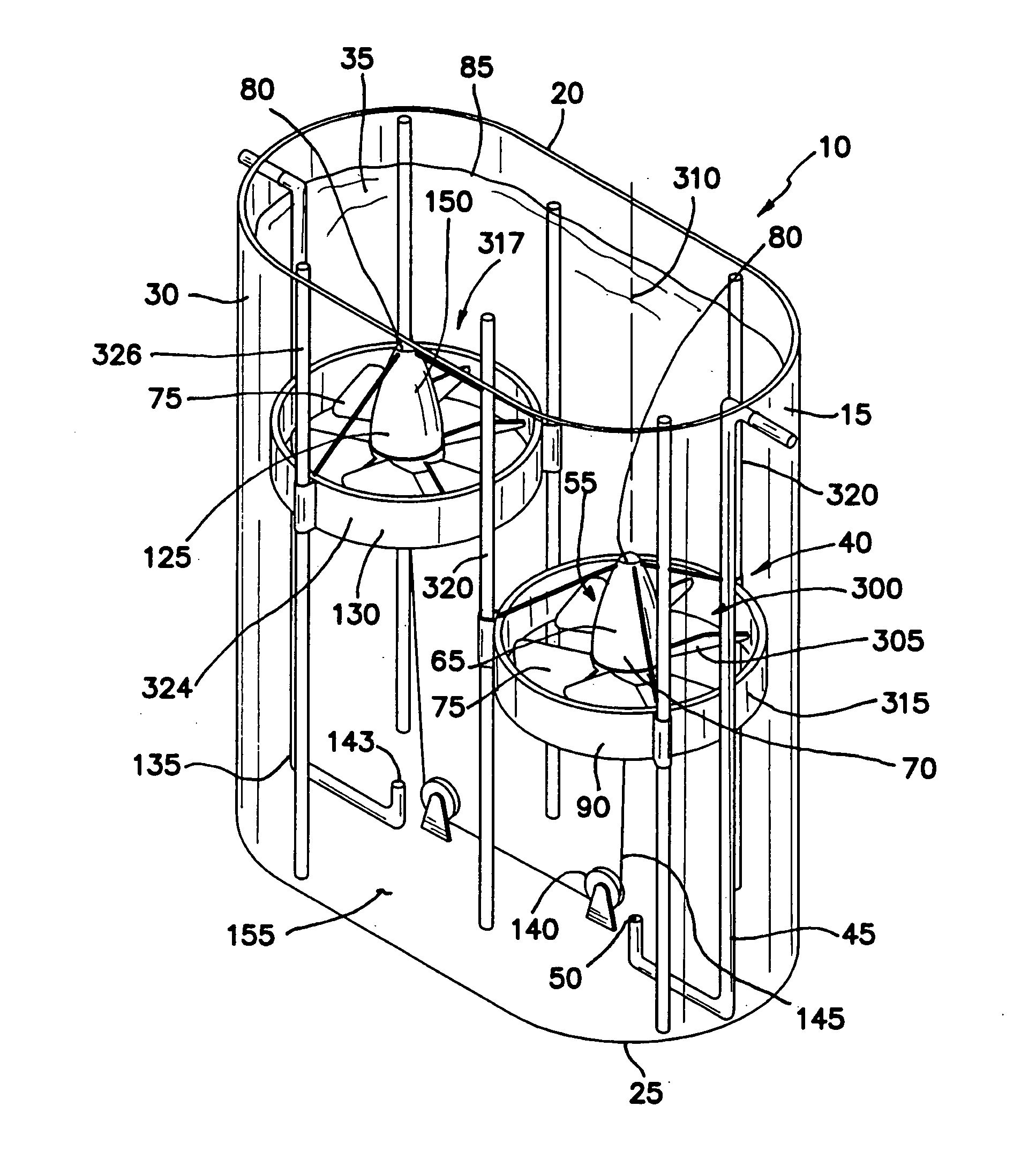
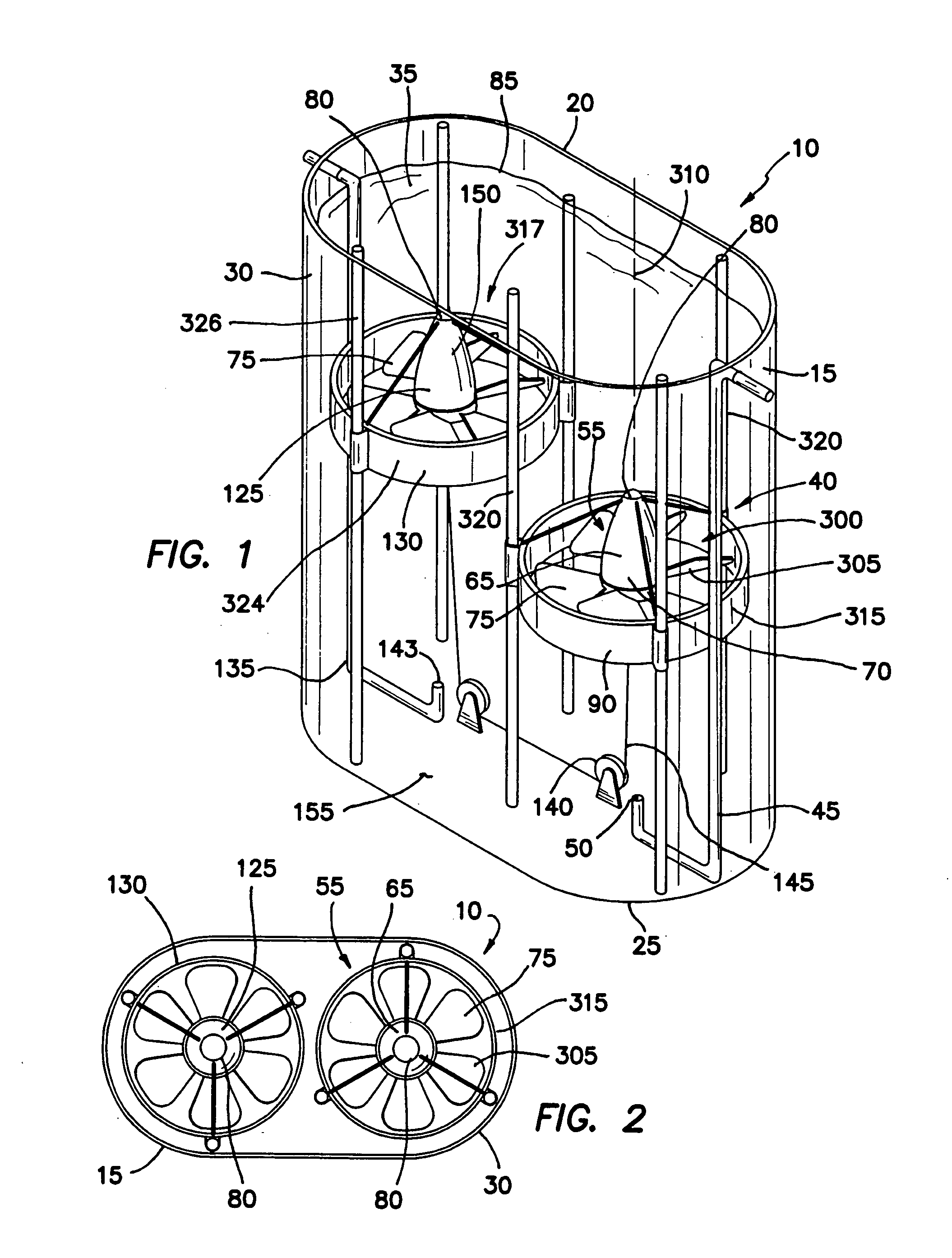
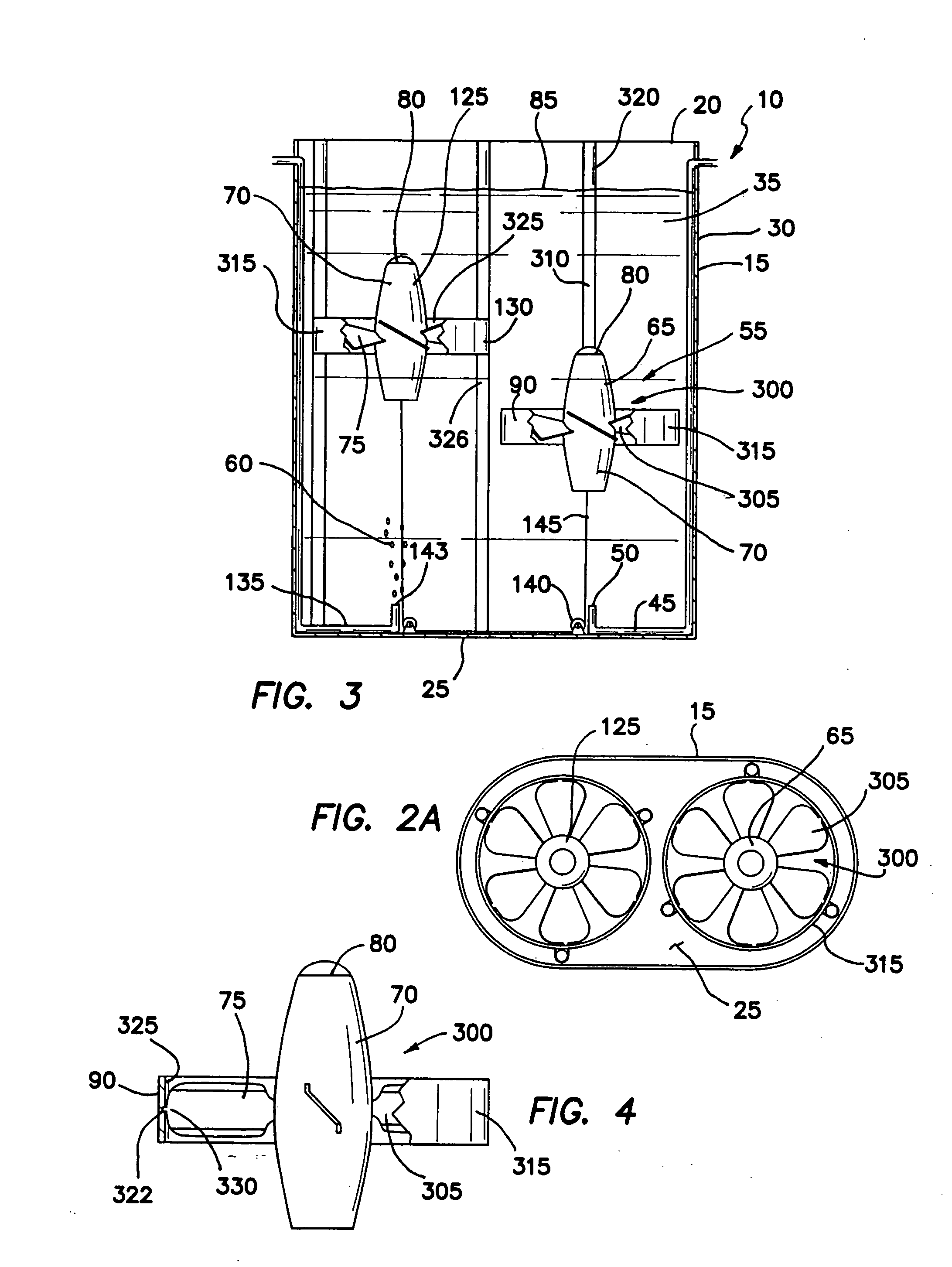
[0058] (1) A pneumatic bioreactor 10, as illustrated in FIGS. 1-3, providing all of the desired features can be constructed from the following components. A containment vessel 15 is provided. The vessel 15 has a top 20, a closed bottom 25, a surrounding wall 30 and is of sufficient size to contain a fluid 35 to be mixed and a mixing apparatus 40. The mixing apparatus 40 includes at least one gas supply line 45. The supply line 45 terminates at an orifice 50 adjacent the bottom 25 of the vessel 15. At least one buoyancy-driven mixing device 55 is provided. The mixing device 55 moves in the fluid 35 as gas 60 from the supply line 45 is introduced into and vented from the mixing device 55. When gas 60 is introduced into the gas supply line 45 the gas 60 will enter the mixing device 55 and cause the device to mix the fluid 35.

[0059] (2) In a variant of the invention, the buoyancy-driven mixing device 55 further includes at least one floating mixer 65. The mixer 65 has a central, gas-ho...


PUM

PropertyMeasurementUnit
Temperatureaaaaaaaaaa
Pressureaaaaaaaaaa
Weightaaaaaaaaaa

Abstract

A pneumatic bioreactor includes a vessel containing a fluid to be mixed and at least one mixing device driven by gas pressure. A first embodiment includes a floating impeller that rises and falls in the fluid as gas bubbles carry it upward to the surface where the gas is then vented, permitting the impeller to sink in the fluid. The floating impeller may be tethered to a second impeller with a flexible member and pulley. The mixing speed is controlled with electromagnets in the vessel acting upon magnetic material in the impeller or its guides. In another embodiment, floating pistons mix the fluid, pushing it through a mixing plate with one or more apertures. In a third embodiment, the mixing device is a rotating drum with bubble-catching blades and rotating mixing plates with apertures. The top of the vessel for these mixers may include a closed top and sterile filters.

Description

FIELD OF INVENTION [0001] The invention pertains to apparatus for mixing solutions. More particularly, the invention relates to pneumatically operated mixers for use in closed, sterile environments. BACKGROUND OF THE INVENTION [0002] Bioreactors have been used for cultivation of microbial organisms for production of various biological or chemical products in the pharmaceutical, beverage and biotechnological industry. A production bioreactor contains culture medium in a sterile environment that provides various nutrients required to support growth of the biological agents of interest. Conventional bioreactors use mechanically driven impellors to mix the liquid medium during cultivation. The bioreactors can be reused for the next batch of biological agents after cleaning and sterilization of the vessel. The procedure of cleaning and sterilization requires a significant amount of time and resources, especially, to monitor and to validate each cleaning step prior to reuse for production...

Claims


Application Information

Patent Timeline
IPC IPC(8): B01F13/00B01F33/40
CPCB01F3/04113B01F3/04602B01F7/00483B01F11/0082C12M27/06B01F15/00525C12M23/56C12M27/02B01F15/005B01F23/23105B01F23/2334B01F27/1154B01F31/441B01F35/3203B01F35/32015C12M1/06B01F33/00
Inventor ZEIKUS, J. GREGORY
Owner PBS BIOTECH INC
Why Eureka
Try Eureka