
Automatic system for adjusting the trim of a motor boat

a technology for automatic adjustment and motor boats, which is applied in the direction of waterborne vessels, vessel parts, marine propulsion, etc., can solve the problems of no longer horizontal boat with respect to water, no longer horizontal propulsive force generated by the prop, and decrepit the efficiency of the motor/prop combination

Active Publication Date: 2007-04-26
CSOKE LAJOS
View PDF18 Cites 6 Cited by
  • Summary
  • Abstract
  • Description
  • Claims
  • Application Information

AI Technical Summary

Benefits of technology

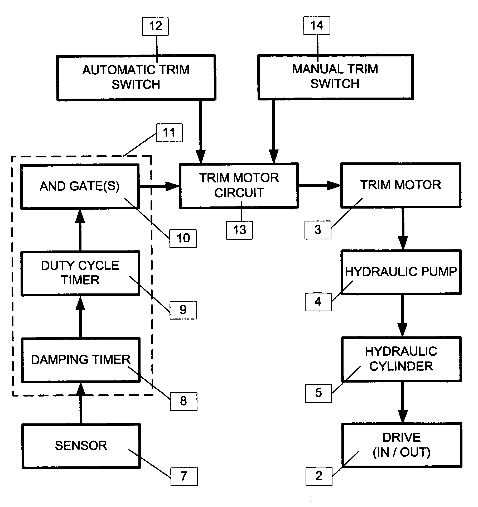
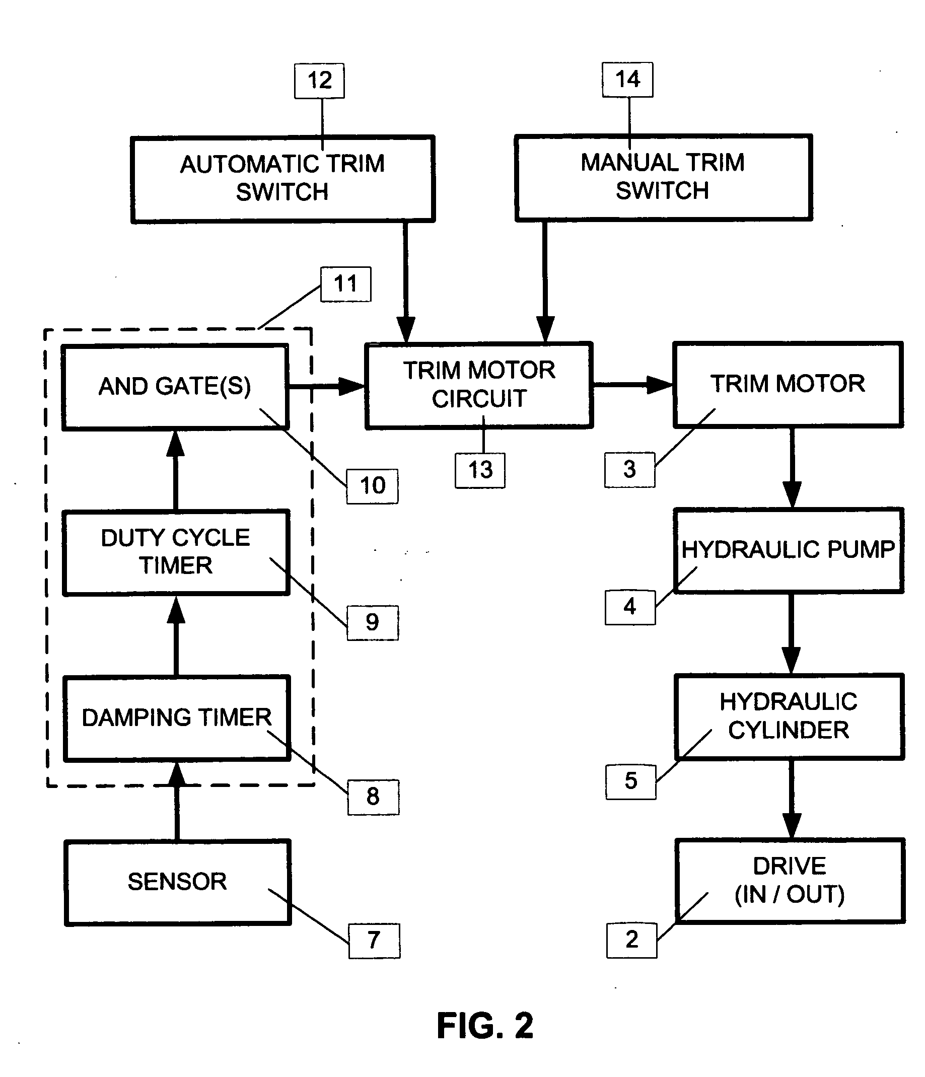
[0004] In accordance with the present invention, there is provided a system for automatically controlling the trim of a boat drive thrust on a boat by controlling the trim motor which adjusts the trim angle of the boat drive thrust by pivoting the boat drive thrust relative to the boat. The system includes a control unit operatively coupled to the trim motor. The control unit causes the trim motor to adjust the trim of the boat drive thrust towards the horizontal when the control unit is activated. A trim sensor is provided on the boat drive thrust to measure the trim of...

Problems solved by technology

As the bow of the boat rises, the angle of the boat changes and the angle at which the prop sits in the water changes, thereby decreasing the efficiency of the motor / prop combination.
However, as the bow of the boat rises, the boat no longer remains horizontal with respect to the water, and the prop is placed at an angle.
As a result, the propulsive force generated by the prop is no longer horizontally directed.
These proposals are rather complex, usually involving subsystems for measuring the boats speed and micro-processors for calculating the optimum trim angle and controlling the trim motors.
While potentially effective, these systems are expensive to implement.

Method used


Image

  • Automatic system for adjusting the trim of a motor boat
  • Automatic system for adjusting the trim of a motor boat
  • Automatic system for adjusting the trim of a motor boat

Examples


example

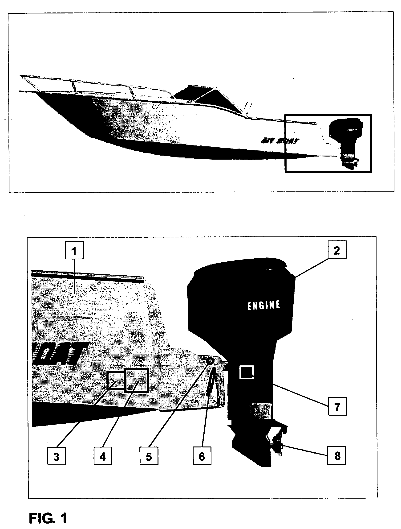
[0016] To test the invention, the automatic system for adjusting the trim of a motor boat as described above was applied to a test boat. The test boat consisted of 19 foot long boat having a dry weight of 1800 lbs, a fuel capacity of 50 gallons and driven by a 175 hp trim-able motor with a 14×21 inch propeller installed. The sensor consisted of a 13.2 mm diameter tubed bent to a radius of arch of 130 mm and filled with a liquid of dynamic viscosity 25 centistokes at 20 degrees C. A steal ball having a diameter of 12 mm was placed inside the tube and the ends of the tube were closed with plug-type contacts. The damping timer was set to 7 seconds and the duty cycle timer set to 2 seconds ON and 5 seconds OFF. Tests were done in light wind conditions with random waves of 1 to 2 feet in magnitude. The test boat performed well reaching a top speed of 47.3 MPH at 5200 rpm.

[0017] The present system has several advantages over the prior art. Firstly, the sensor is quite inexpensive to buil...


PUM


Abstract

The present invention is a system for automatically controlling the trim of a boat drive thrust on a boat by controlling the trim motor which adjusts the trim angle of the boat drive thrust by pivoting the boat drive thrust relative to the boat. The system includes a control unit operatively coupled to the trim motor. The control unit causes the trim motor to adjust the trim of the boat drive thrust towards the horizontal when the control unit is activated. A trim sensor is provided on the boat drive thrust to measure the trim of the boat drive thrust. The trim sensor is operatively coupled to the control unit and is configured to send an activation signal to the control unit to activate the control unit when the sensor senses that the boat drive thrust is at a predetermined angle from the horizontal. The trim sensor consist of a pendulum movable between first and second electronic contacts, the sensor being configured to send the activation signal when the pendulum engages one of the electronic contacts. The trim sensor further includes a dampening mechanism for slowing the movement of the pendulum.

Description

FIELD OF THE INVENTION [0001] The invention relates generally to systems for automatically adjusting the trim of motor boats. BACKGROUND OF THE INVENTION [0002] It is a well known characteristic of motor boats that when under power, the bow of the boat tends to rise. As the bow of the boat rises, the angle of the boat changes and the angle at which the prop sits in the water changes, thereby decreasing the efficiency of the motor / prop combination. Ideally, the boat's prop is held horizontally in the water in order to maximize the efficiency of the prop and motor. With the prop held in a horizontal position, all of the propulsive force generated by the prop is directed horizontally in the desired direction. However, as the bow of the boat rises, the boat no longer remains horizontal with respect to the water, and the prop is placed at an angle. As a result, the propulsive force generated by the prop is no longer horizontally directed. Therefore, to maintain the maximum efficiency of ...

Claims


Application Information

Patent Timeline
IPC IPC(8): B63H20/08
CPCB63H20/10
Inventor CSOKE, LAJOS
Owner CSOKE LAJOS
Learn More