Apparatus and method for a system architecture for multiple antenna wireless communication systems using round robin channel estimation and transmit beam forming algorithms

a wireless communication system and antenna technology, applied in the field of wireless communication, can solve the problems of much longer battery life of the receiver, achieve the effect of simple low cost transmitter, improve transmission efficiency, and improve transmission efficiency

Active Publication Date: 2007-04-26
RGT UNIV OF CALIFORNIA
View PDF8 Cites 73 Cited by
  • Summary
  • Abstract
  • Description
  • Claims
  • Application Information

AI Technical Summary

Benefits of technology

[0012] The disclosed system architecture is intended for multiple antenna wireless systems. This disclosed architecture enables a simple low cost transmitter and receiver design for practical wireless communication devices. In this disclosure, we describe a novel transmit beamforming scheme based on a reconfigurable large antenna array (LAA). Compared to the conventional schemes, our scheme requires a much smaller number of RF chains, yet it still enjoys the high performance offered from the LAA. Based on a reconfigurable LAA, we present a pilot assisted round robin channel estimation algorithm. With this estimation algorithm, the tracking of the fading channel is significantly simplified at the mobile station. We then introduce an adaptive transmit beamforming algorithm based on relative channel phase feedback at the transmitter. For a time varying Rayleigh fading channel, we investigate the system signal-to-noise ratio (SNR) as a function of the latency of the round robin channel estimation and derive the optimal training duration for given mobile speed. Finally, numerical simulations show that the proposed scheme accomplishes superior performance for various kinds of time varying Rayleigh fading channels. Overall, the proposed system enjoys good performance, high flexibility, low cost as well as low power consumption at both the base station and mobile station.
[0017] b. Simple transmitter design: The illustrated embodiment of the system architecture uses only a small amount of RF chains at the transmitter. Thus the cost, power consumption, implementation complexity of the transmitter is reduced.
[0018] c. Efficient receiver design: At any given time, the receiver only needs to estimate the channel path gain from one particular transmit antenna. Therefore, the channel estimation task is significantly simplified at the receiver. As a result, the receiver enjoys much longer battery life.
[0022] The pilot assisted round robin channel estimation means and the adaptive transmit beamforming means operate at an optimal training duration for a given mobile speed of the receiver.

Problems solved by technology

As a result, the receiver enjoys much longer battery life.

Method used


Image

  • Apparatus and method for a system architecture for multiple antenna wireless communication systems using round robin channel estimation and transmit beam forming algorithms
  • Apparatus and method for a system architecture for multiple antenna wireless communication systems using round robin channel estimation and transmit beam forming algorithms
  • Apparatus and method for a system architecture for multiple antenna wireless communication systems using round robin channel estimation and transmit beam forming algorithms

Examples


Embodiment Construction

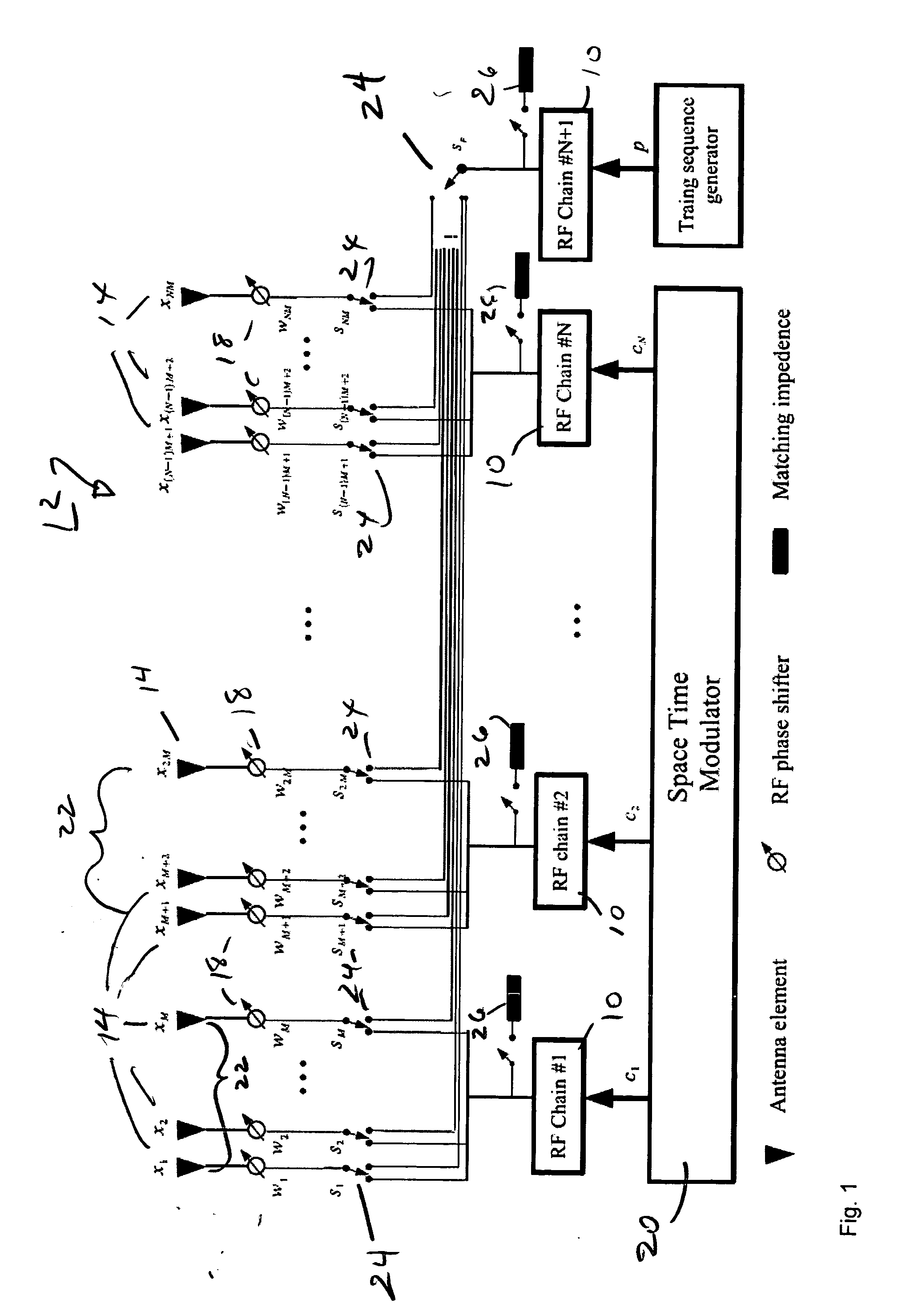
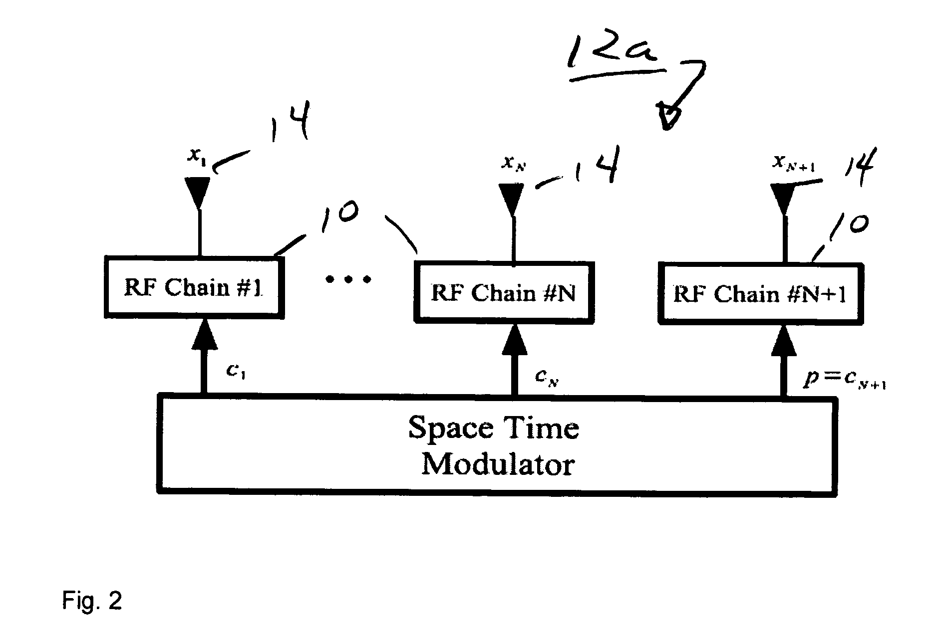
[0050] In the illustrated embodiment we use an adaptive transmit beamforming scheme. In the illustrated embodiment of FIG. 1, only a small number of RF chains 10 are implemented at the transmitter or large antenna array 12. These RF chains 10 are divided into two groups. The first group is employed to drive all the transmit antennas 14 for normal data transmissions, while the next group has only one RF chain and it is used to transmit pilot training sequence on certain “selected” transmit antennas 14. The pilot sequence is transmitted by different ones of the selected antennas 14 in a round-robin fashion. At any time, the receiver (not shown) only needs to estimate a few channel path gains without interrupting the ongoing data communications. As the receiver gathers enough knowledge of the channel, it sends back the relative channel phase information to the transmitter 12. On the transmitter side, the RF phase shifters 18 in the LAA are adjusted to perform a standard co-phase transm...


PUM


Abstract

A multiple antenna wireless system including a transmitter and a receiver comprises a reconfigurable large antenna array having a plurality of antennas. A plurality of RF chains in the transmitter is coupled to the reconfigurable large antenna array. A pilot assisted round robin channel estimation means tracks the fading channel; and an adaptive round robin transmit beamforming means beam forms the reconfigurable large antenna array. A method for multiple antenna wireless communication comprising the steps of tracking a plurality of fading channels in a reconfigurable large antenna array having a plurality of antennas using pilot assisted round robin channel estimation to selectively couple a plurality of RF chains in the transmitter to the reconfigurable large antenna array, and adaptively, round-robin transmit beamforming the reconfigurable large antenna array.

Description

RELATED APPLICATIONS [0001] The present application is related to U.S. Provisional Patent Application, Ser. No. 60 / 730,181, filed on Oct. 24, 2005, which is incorporated herein by reference and to which priority is claimed pursuant to 35 USC 119.GOVERNMENT RIGHTS [0002] This invention is supported in part by the Contract ECS-0424454 from the National Science Foundation. The U.S. Government has certain rights.BACKGROUND OF THE INVENTION [0003] 1. Field of the Invention [0004] The invention relates to the field of wireless communications in which channel estimation and transmit beam forming occurs in a reconfigurable antenna array. [0005] 2. Description of the Prior Art [0006] Many space-time transmission schemes have been proposed recently to exploit the high channel capacity from the MIMO communication systems. However, algorithms for a large antenna array (LAA) remain an open research problem. The standard channel estimation and space-time modulation schemes are not practical for L...

Claims


Application Information

Patent Timeline
Patent Type & Authority Applications(United States)
IPC IPC(8): H04M1/00
CPCH04B7/0617H04B7/0626
Inventor JAFARKHANI, HAMIDLIU, LI
Owner RGT UNIV OF CALIFORNIA
Why Eureka
Try Eureka