
Method of table mounted retraction in hip surgery and surgical retractor

a hip and surgical technology, applied in the field of surgical retraction, can solve the problems of complex operation, severe discomfort, and inability to view the surgical site, and achieve the effects of comfort, and improving the patient's comfor

Inactive Publication Date: 2007-04-26
MINNESOTA SCI
View PDF76 Cites 22 Cited by
  • Summary
  • Abstract
  • Description
  • Claims
  • Application Information

AI Technical Summary

Benefits of technology

[0008] The present invention includes a method of performing a hip joint surgery on a patient positioned on a surgical table where the hip joint includes a pelvis having an acetabulum, a femur and a femoral ball. The method includes mounting a retractor support to the surgical table. The retractor support is positioned about the hip joint and about an incision into the skin and flesh layers proximate the hip joint. A blade portion of a retractor is positioned within the incision and the skin and flesh layers are manually retracted proximate the hip joint. A handle portion of the retractor is pivoted with respect to the blade portion to position the handle portion in a selected position. The handle portion is secured in a selected position by attaching the handle portion to the retractor support.

Problems solved by technology

The surrounding structures in the hip can become inflamed and painful.
Eventually, bone can begin to rub against bone causing severe discomfort.
The ability to view the surgical site is complicated by the need to remove the femoral head from the acetabulum as well as rotate and retract the femur in the wound during surgery.
Depending on the size of the patient, the strenuous activity can lead to fatigue and contribute to surgical error.
Additionally, the repeated movement of the leg can cause nerve damage if it is not done precisely and with minimal adjustment.
Often, the surgeon holding the leg relaxes or becomes fatigued and allows the leg to move, requiring that the leg be readjusted.
The movement can cause the leg to pinch or rub nerves or muscle tissue, possibly causing damage.

Method used


Image

  • Method of table mounted retraction in hip surgery and surgical retractor
  • Method of table mounted retraction in hip surgery and surgical retractor
  • Method of table mounted retraction in hip surgery and surgical retractor

Examples


Embodiment Construction

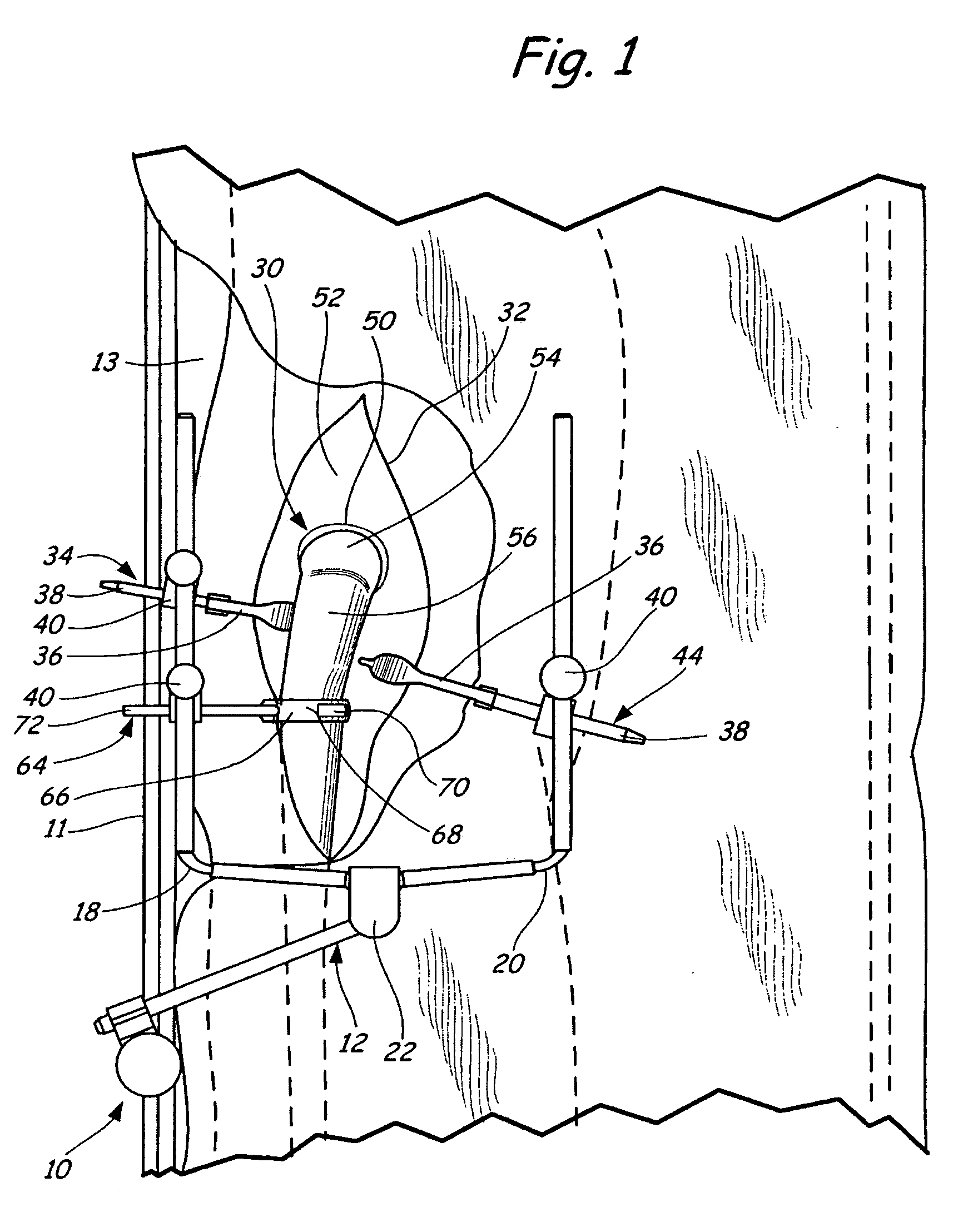
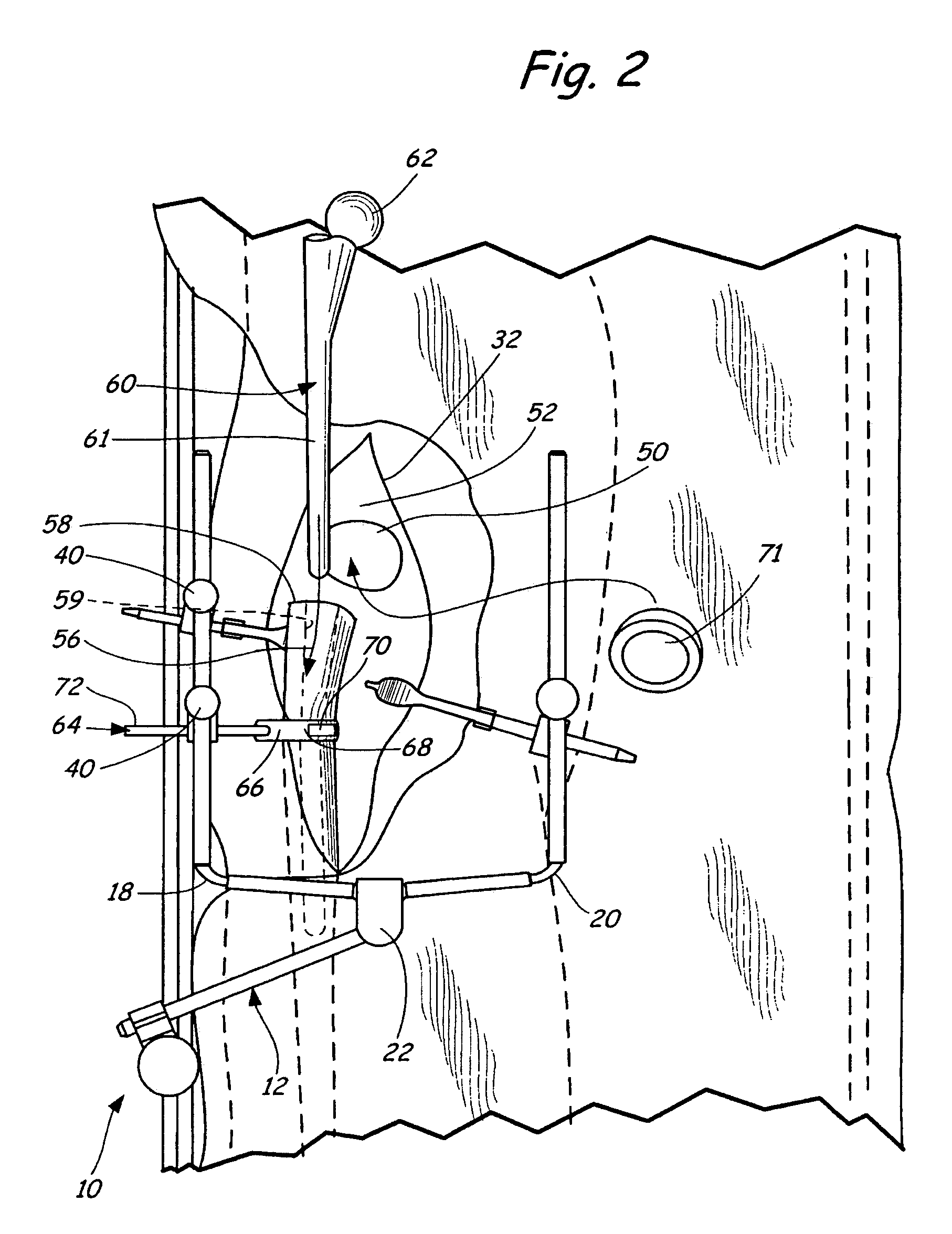
[0015] The present invention relates to a method of performing surgical procedures on or proximate a hip joint. An apparatus used in the surgical procedures of the present invention is generally indicated at 10 in FIG. 1.

[0016] The apparatus 10 includes a retractor support apparatus 12 that is rigidly mounted to a rail 11 of a surgical table 13 in a manner that is well known in the art and is described in U.S. Pat. Nos. 4,617,916, 4,718,151, 4,949,707, 5,400,772, 5,741,210, 6,042,541, 6,264,396 and 6,315,718 all of which are herein incorporated by reference. From the mount to the surgical table 13, the retractor support apparatus 12 includes left and right support arms 18 and 20 that extend over the surgical table 13. The support arms 18 and 20 are independently adjustable into an infinite number of selected positions through use of a clamping mechanism 22 which is described in U.S. Pat. Nos. 5,899,627 and 6,264,396, which are herein incorporated by reference. The support arms 18 a...


PUM


Abstract

A method of performing a hip joint surgery on a patient includes positioning the patient on a surgical table where the hip joint includes a pelvis having an acetabulum, a femur and a femoral ball. The method includes mounting a retractor support to the surgical table. The retractor support is positioned about the hip joint and about an incision into the skin and flesh layers proximate the hip joint. A blade portion of a retractor is positioned within the incision and the skin and flesh layers are manually retracted proximate the hip joint. A handle portion of the retractor is pivoted with respect to the blade portion to position the handle portion in a selected position. The handle portion is secured in a selected position by attaching the handle portion to the retractor support.

Description

CROSS REFERENCE TO RELATED APPLICATIONS [0001] This application is a continuation-in-part of Application No. 11 / 032,548 filed on Jan. 10, 2005 which is hereby incorporated by reference in its entirety, which is a continuation-in-part of Application No. 10 / 728,202 filed on Dec. 4, 2003, which is hereby incorporated by reference in its entirety, which is a continuation of Application No. 10 / 077,693, filed Feb. 15, 2002, which is incorporated by reference in its entirety, and resulting in U.S. Pat. No. 6,659,944, which is a continuation of Application No. 09 / 990,420 filed on Nov. 21, 2001, which is incorporated by reference in its entirety, and resulting in U.S. Pat. No. 6,368,271. [0002] This application is also a continuation-in-part of Application No. 10 / 892,816 filed on Jul. 16, 2004, which is hereby incorporated by reference in its entirety, which is a continuation-in-part of Application No. 10 / 623,179; filed Jul. 18, 2003, which is hereby incorporated by reference in its entirety...

Claims


Application Information

Patent Timeline
Patent Type & Authority Applications(United States)
IPC IPC(8): A61B1/32
CPCA61B17/02A61B17/0206A61B19/26A61B90/50
Inventor SHARRATT, TODD W.
Owner MINNESOTA SCI
Learn More