In vivo accessories for minimally invasive robotic surgery
What is AI technical title?
AI technical title is built by Patsnap AI team. It summarizes the technical point description of the patent document.
a robotic surgery and robotic surgery technology, applied in the field of in vivo accessories for minimally invasive robotic surgery, can solve the problems of reducing the cost of hospital residency, reducing the cost of hospitalization, so as to minimize the “down time”
Inactive Publication Date: 2007-04-26
INTUITIVE SURGICAL OPERATIONS INC
View PDF23 Cites 37 Cited by
Summary
Abstract
Description
Claims
Application Information
AI Technical Summary
This helps you quickly interpret patents by identifying the three key elements:
Problems solved by technology
Method used
Benefits of technology
Benefits of technology
[0009] The present invention is generally directed to robotic surgery methods, devices, and systems. The invention overcomes the problems and disadvantages of the prior art by providing surgical clips and / or other in vivo accessories at the surgical site. These in vivo accessories can be manipulated by robotic surgical tools in the site for performing different tasks. The accessories can be held by a dedicated accessory holder or support that is introduced into the surgical site through a separate opening. Alternatively, the accessories can be supported on the body of one of the surgical tools, and can be manipulated using another surgical tool in the surgical site. The surgical tools in the surgical site can use the accessories for performing a wide range of additional tasks without leaving the surgical site. In this way, the need to exchange tools and load instruments outside the surgical site is reduced, thereby minimizing “down time”.
[0014] In some embodiments, a portion of a master control device located remotely from the patient is actuated by a user to control the robotic surgical tool to grasp the surgical accessory. The robotic surgical tool may be instructed to continue to grasp the surgical accessory without requiring the user to continue to actuate the actuatable portion of the master control device.
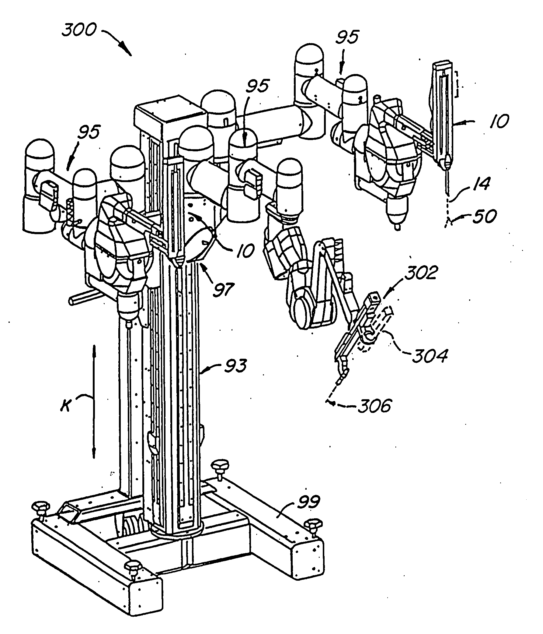
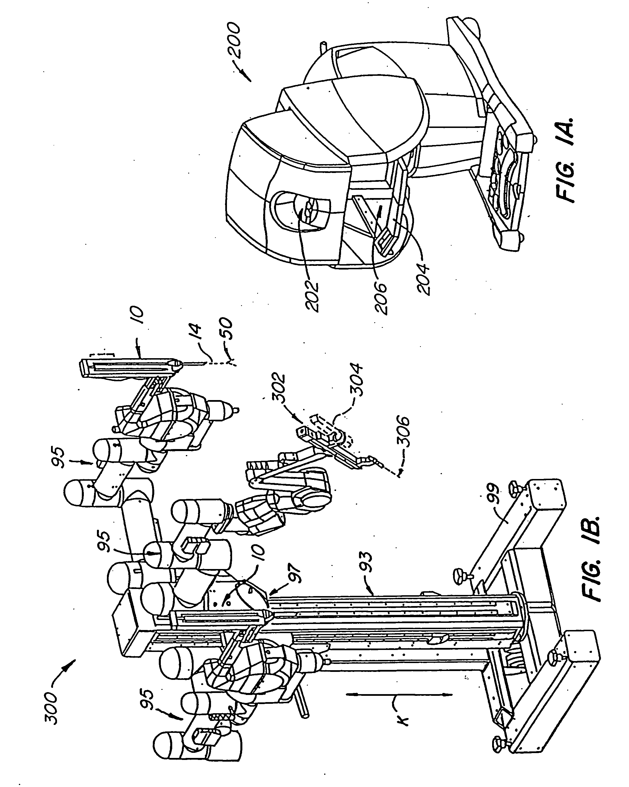
[0017] Another aspect of the present invention is directed to a robotic surgical system for effecting a predetermined treatment of a target tissue at an internal surgical site within a patient body. The system includes a surgical accessory adapted for effecting the treatment, and an accessory introducer having a proximal end and a distal end with an opening therebetween. The distal end of the introducer is insertable into the patient body so that the opening defines a first minimally invasive aperture. The surgical accessory is coupled with the distal end of the introducer and is passable through the opening to the internal surgical site. A robotic arm supports a surgical tool having an end effector suitable for insertion through a second minimally invasive aperture to the internal surgical site. The end effector is coupleable with the surgical accessory within the internal surgical site so that the robot arm can manipulate the surgical accessory to direct the treatment to the target tissue.
Problems solved by technology
Thus, an increased adoption of minimally invasive techniques could save millions of hospital days, and millions of dollars annually in hospital residency costs alone.
There are many disadvantages relating to current minimally invasive surgical (MIS) technology.
For example, existing MIS instruments deny the surgeon the flexibility of tool placement found in open surgery.
Most current laparoscopic tools have rigid shafts, so that it can be difficult to approach the worksite through the small incision.
Additionally, the length and construction of many endoscopic instruments reduces the surgeon's ability to feel forces exerted by tissues and organs on the end effector of the associated tool.
The lack of dexterity and sensitivity of endoscopic tools is a major impediment to the expansion of minimally invasive surgery.
Tool exchange and instrument loading for a robotic system takes time.
Providing additional surgical instruments in the surgical site (and the typically associated need to make additional incisions in the patient's body) may be an undesirable alternative for any number of reasons, e.g., due to space constraints, increase in system complexities, and / or cost.
Method used
Image
Click on the blue label to locate the original text in one second.
Reading with bidirectional positioning of images and text.
Examples
Embodiment Construction
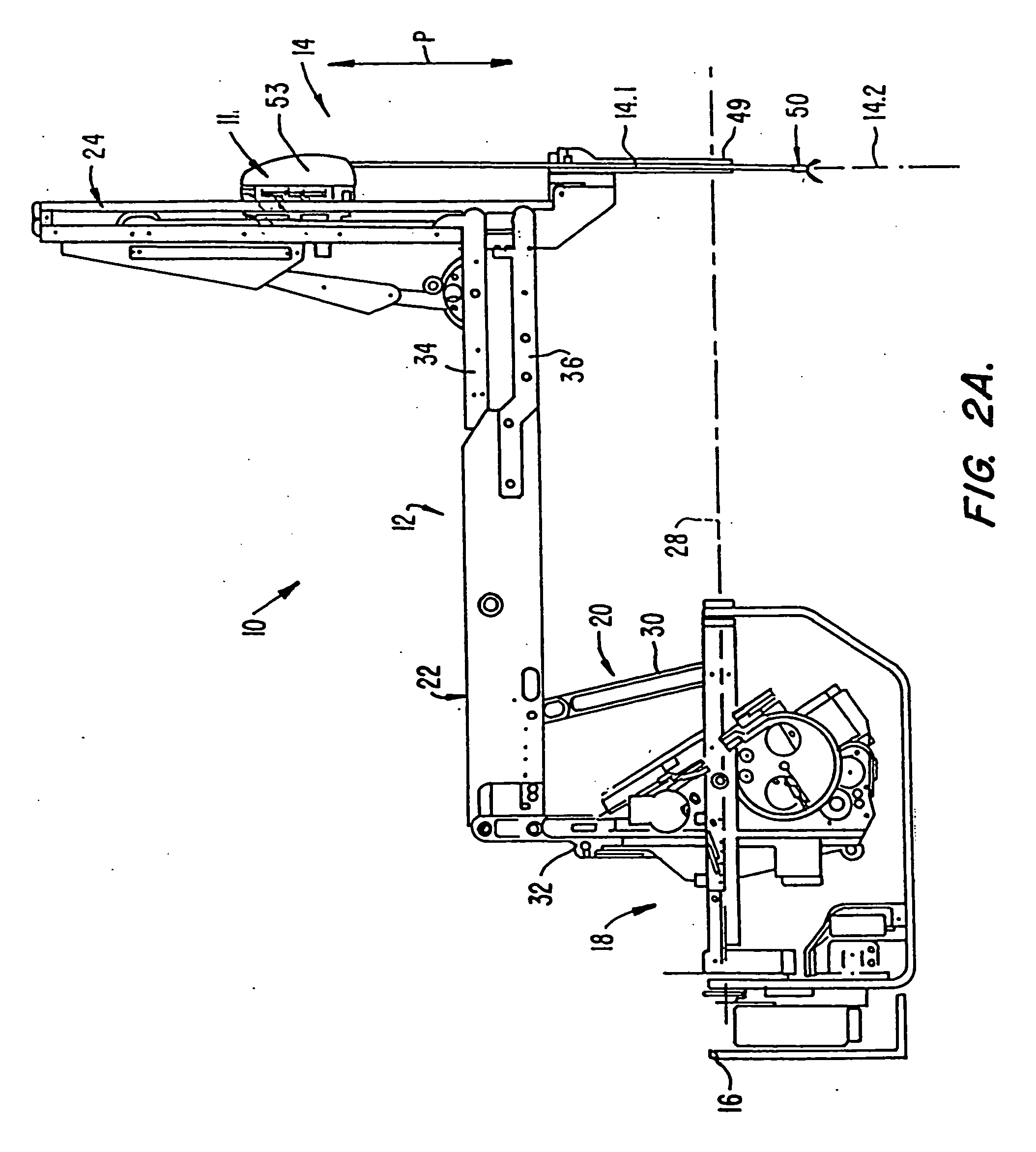
[0054] As used herein, “end effector” refers to the actual working part that is manipulatable for effecting a predetermined treatment of a target tissue. For instance, some end effectors have a single working member such as a scalpel, a blade, or an electrode. Other end effectors have a pair of working members such as forceps, graspers, scissors, or clip appliers, for example.
[0055] As used herein, the terms “surgical instrument”, “instrument”, “surgical tool”, or “tool” refer to a member having a working end which carries one or more end effectors to be introduced into a surgical site in a cavity of a patient, and is actuatable from outside the cavity to manipulate the end effector(s) for effecting a desired treatment of a target tissue in the surgical site. The instrument or tool typically includes a shaft carrying the end effector(s) at a distal end, and is preferably servo mechanically actuated by a telesurgical system for performing functions such as holding or driving a needl...
PUM
Abstract
Surgical accessories are presented in vivo and used by surgical tools in the surgical site to perform additional tasks without the need to remove the tools from the surgical site for tool change or instrument loading. Examples of in vivo accessories include fastening accessories such as surgical clips for use with a clip applier, single working member accessories such as a blade which can be grasped and manipulated by a grasping tool for cutting, sheath accessories that fit over working members of a tool, flow tubes for providing suction or introducing a fluid into the surgical site, and a retraction member resiliently biased to retract a tissue to expose an area in the surgical site for treatment. The accessories can be introduced into the surgical site by a dedicated accessory introducer, or can be supported on the body of a surgical tool inserted into the surgical site and be manipulated using another surgical tool in the surgical site. The accessory introducer can be resiliently biased to bias the accessories toward a predetermined position in the surgical site.
Description
CROSS-REFERENCES TO RELATED APPLICATIONS [0001] This application is a continuation-in-part of and claims benefit from U.S. patent application Ser. No. 09 / 478,953, filed Jan. 7, 2000, which is a continuation-in-part of U.S. patent application Ser. No. 09 / 453,978, filed Dec. 2, 1999, the complete disclosures of which are incorporated herein by reference. [0002] This application is related to the following patents and patent applications, the full disclosures of which are incorporated herein by reference: PCT International Application No. PCT / US98 / 19508, entitled “Robotic Apparatus”, filed on Sep. 18, 1998, U.S. application Ser. No. 09 / 418,726, entitled “Surgical Robotic Tools, Data Architecture, and Use”, filed on Oct. 15, 1999; U.S. Application Ser. No. 60 / 111,711, entitled “Image Shifting for a Telerobotic System”, filed on Dec. 8, 1998; U.S. application Ser. No. 09 / 378,173, entitled “Stereo Imaging System for Use in Telerobotic System”, filed on Aug. 20, 1999; U.S. application Ser....
Claims
Application Information
Patent Timeline
Application Date:The date an application was filed.
Publication Date:The date a patent or application was officially published.
First Publication Date:The earliest publication date of a patent with the same application number.
Issue Date:Publication date of the patent grant document.
PCT Entry Date:The Entry date of PCT National Phase.
Estimated Expiry Date:The statutory expiry date of a patent right according to the Patent Law, and it is the longest term of protection that the patent right can achieve without the termination of the patent right due to other reasons(Term extension factor has been taken into account ).
Invalid Date:Actual expiry date is based on effective date or publication date of legal transaction data of invalid patent.
Patent Type & AuthorityApplications(United States)

