Surgical drill, a set of surgical drills, a system for cutting bone and a method for removing bone

Inactive Publication Date: 2007-04-26
HOOGLAND THOMAS
View PDF17 Cites 115 Cited by
  • Summary
  • Abstract
  • Description
  • Claims
  • Application Information

AI Technical Summary

Benefits of technology

[0019] Thus, it is an objective of the present invention to provide a surgical drill and a system for

Problems solved by technology

Such compression of the dural sack and the respective nerve fibres inside the dural sack causes pain, numbness or even paralysis of the patient.
The removal of the bone structure to access the spinal canal is a very deli

Method used


Image

  • Surgical drill, a set of surgical drills, a system for cutting bone and a method for removing bone
  • Surgical drill, a set of surgical drills, a system for cutting bone and a method for removing bone
  • Surgical drill, a set of surgical drills, a system for cutting bone and a method for removing bone

Examples


Embodiment Construction

[0060] This invention is not limited in its application to the details of construction and the arrangement of components set forth in the following description or illustrated in the drawings. The invention is capable of other embodiments and of being practiced or of being carried out in various ways. Also, the phraseology and terminology used herein is for the purpose of description and should not be regarded as limiting. The use of “including,”“comprising,” or “having,”“containing”, “involving”, and variations thereof herein, is meant to encompass the items listed thereafter and equivalents thereof as well as additional items.

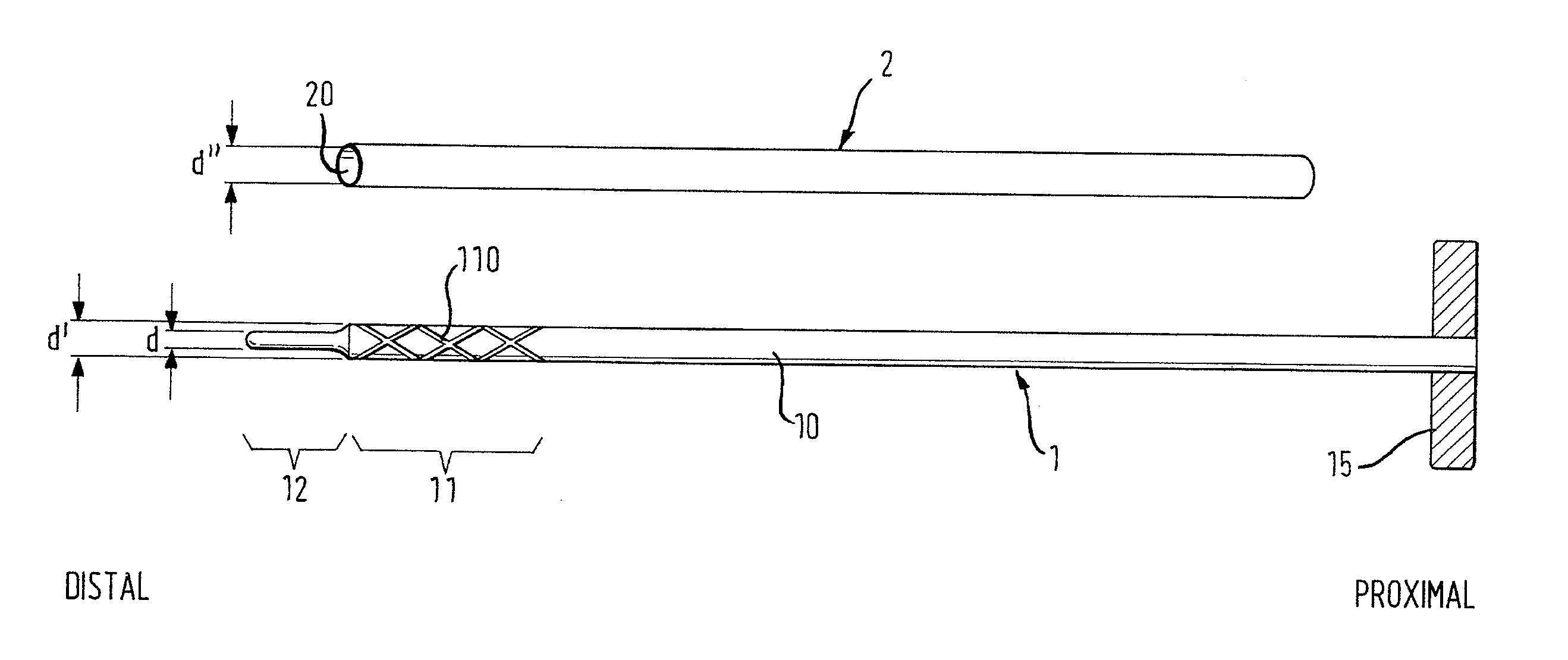
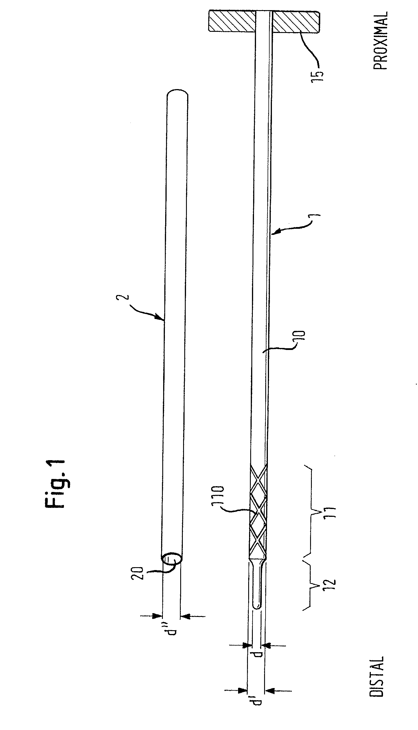
[0061]FIG. 1 shows a surgical drill 1 according to the invention having a drill member 10 with a cutting section 11 and a non-cutting protection tip 12. The cutting section 11 has an outer diameter d′ that corresponds to the diameter that is actually cut into the bone. The cutting section 11 has, furthermore, a drill surface structure 110 for cutting the bone...


PUM


Abstract

The present invention relates to a surgical drill including a drill member having a cutting section for cutting bone, the cutting section being situated at a distal end of the drill member. The drill member also comprises a non-cutting protection tip for protecting nerves, tissue or dura from being cut. The non-cutting protection tip is situated distally of the cutting section.

Description

RELATED APPLICATIONS [0001] This application claims foreign priority benefits under 35 U.S.C. § 119(a)-(d) of the United Kingdom of Great Britain application number GB 0519459.2, filed Sep. 23, 2005. BACKGROUND OF INVENTION [0002] 1. Field of Invention [0003] The present invention relates to a surgical drill according to the pre-characterizing part of claim 1, a set of surgical drills, a system for cutting bone and a method for removing bone. [0004] 2. Discussion of Related Art [0005] In the field of spinal surgery is a need to expose the intraspinal structures by removing parts of the facet joints and the facet joint capsule by a posterior or posterolateral approach. This removal of parts of the bone structure of the spine is carried out in order to access the spinal canal which is filled with nerve structures. The nerve structures in the spinal canal have a weak tissue structure and a tree-like configuration such that the central part of the spinal canal is filled with a long sack...

Claims


Application Information

Patent Timeline
IPC IPC(8): A61B17/00A61B17/16A61B17/17
CPCA61B17/1617A61B17/1633A61B17/164A61B17/1671A61B17/1695A61B17/1697A61B17/1757A61B17/1796A61B2017/00238A61B17/1615A61B17/00A61B17/16A61B17/17
Inventor HOOGLAND, THOMAS
Owner HOOGLAND THOMAS
Why Eureka
Try Eureka