
Structural couplings

a technology of structural couplings and couplings, applied in the direction of structural elements, building components, nuts, etc., can solve the problem of limited use of structures, and achieve the effect of facilitating construction

Inactive Publication Date: 2007-05-03
SINGLETON
View PDF36 Cites 13 Cited by
  • Summary
  • Abstract
  • Description
  • Claims
  • Application Information

AI Technical Summary

Benefits of technology

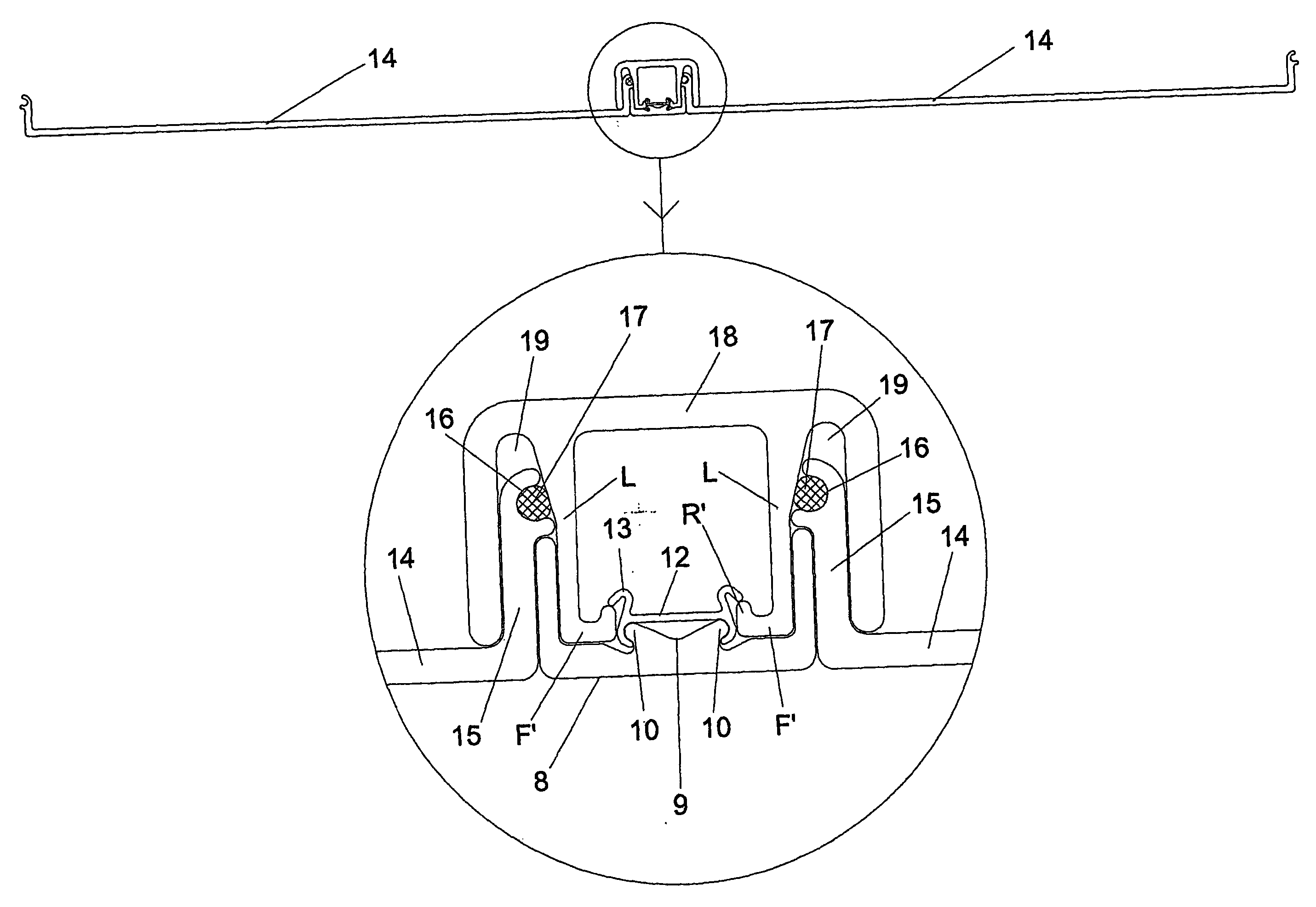
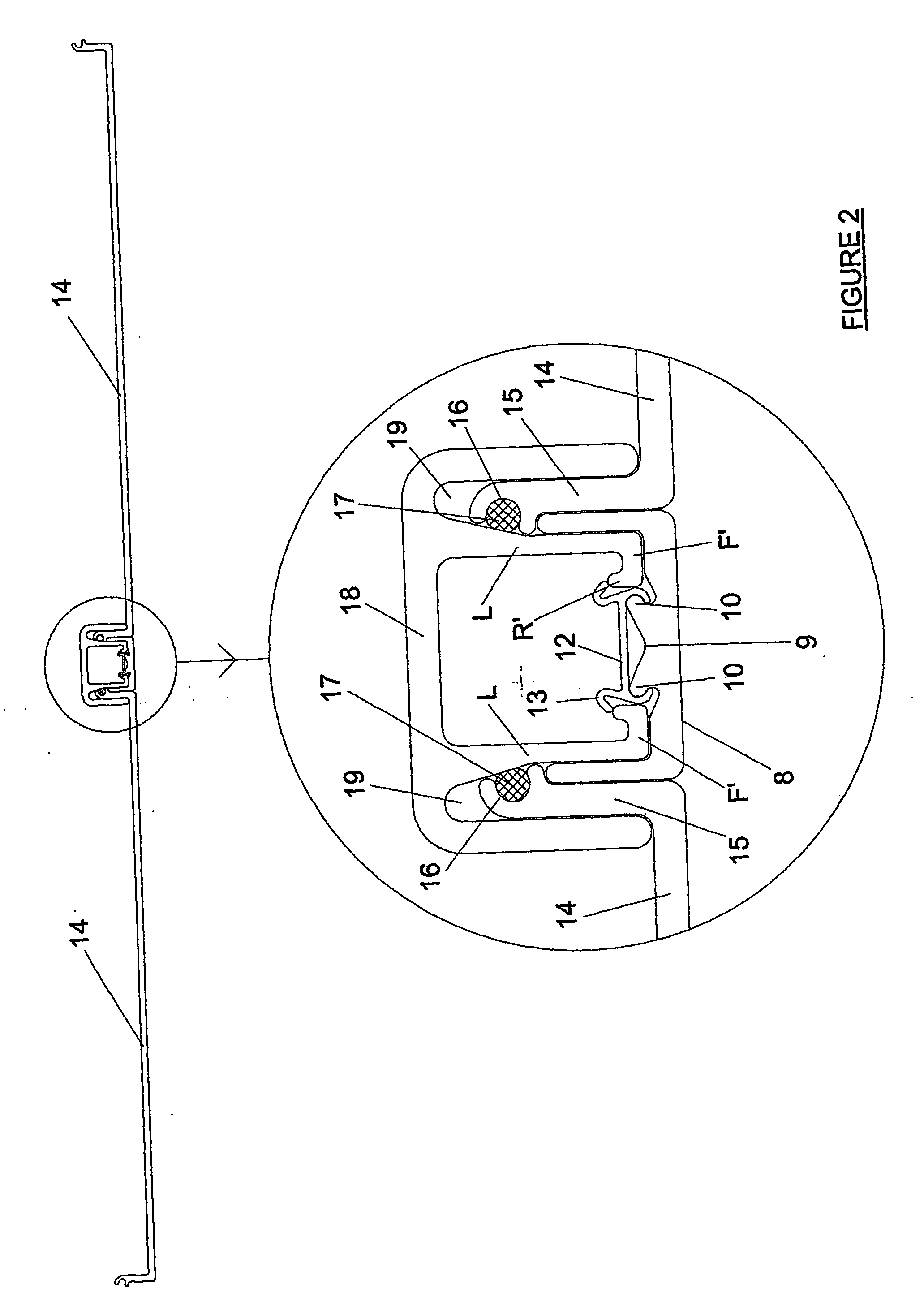
[0011] An object of the invention is to realise the possibility of avoiding the need to connect similar profiles to each other to make frames as in the Unistrut system, but rather to connect the profiles together through the intermediary of a common channel profile. In this way two panels for example can be joined, not directly to each other but to a separate profile to which the common channel connects thereby to facilitate the construction, for example, of a continuous wall with reinforcing struts at every join and to which blind fixings can be made.

Problems solved by technology

A problem with the Unistrut system is its limited use in terms of the structures that can be produced in practice for the reasons explained above.

Method used


Image

  • Structural couplings
  • Structural couplings
  • Structural couplings

Examples


Embodiment Construction

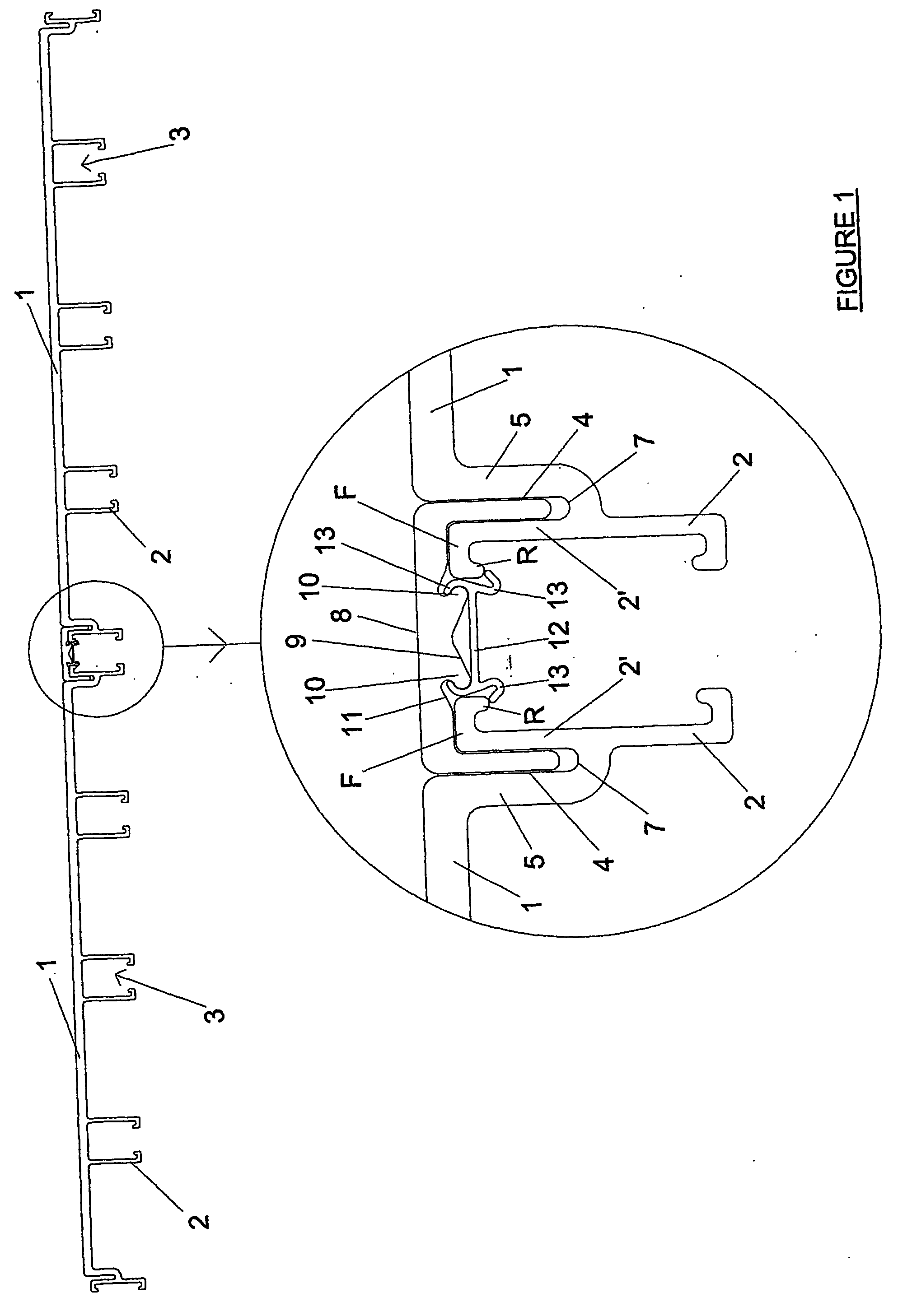
[0022]FIG. 1 shows the invention used to connect together two floor panels 1 which may be of varying width or length to suit requirements.

[0023] The panels 1 have rigidising pairs of opposed L-shaped legs 2 spaced at intervals along the underside surface of the panel 1 to form open box structures 3.

[0024] The opposed edges of the panels 1 are provided with coupling slots 4.

[0025] The coupling slots 4 are formed from a short vertically depending wall portion 5 of the panels 1 and the upper vertical extent 2′ of an end leg 2 of the panels 1 which is spaced from the short wall portion 5 by a short horizontal wall section 7 which forms the base of the coupling slots 4. The vertical extent 2′ of the end leg 2 is provided with an inturned looking flange F provided with a locking rib formation R.

[0026] The downward vertical extent of the end leg 2 from the short horizontal wall section 7 forming the base of each of the coupling slots 4, is equal to the vertical extent of the legs 2, wh...


PUM


Abstract

The present invention relates to structural couplings for forming of a variety of structures such as floor and wall panels for buildings and internal structures such as hand rails. The structural coupling comprises a structural component or components (1) provided with coupling leg formations (2) and locking flanges (F) and a channel section (8) which interconnect one with the other by means of a snap fit engagement (12) of the leg formations (2) of the structural component (1) with the channel section (8). This has considerable advantages over the prior art where nuts and bolts were needed to fasten the components together. The use of a common channel section which can be engaged by snap fit action provides an elegant and non-limited method of joining structural components together rather than in a direct fashion as with prior systems.

Description

FIELD OF THE INVENTION [0001] The present invention relates to structural couplings for forming a variety of structures such as floor and wall panels for buildings and internal structures such as hand rails. BACKGROUND OF INVENTION [0002] Unistrut channels for forming a variety of structures are well known. [0003] The Unistrut system employs channel sections made exclusively of steel which vary only in overall profile height and the thickness of the steel used. Each Unistrut channel in practice is available alone or welded to one or more pieces of the same section in various arrangements or to thin continuous steel plate to present a varied range of steel structural profiles to which blind connections can be made using Unistrut nuts and screws. [0004] A range of flat and folded, pre-drilled steel plates are available with the Unistrut system to connect channels together in different ways to create frame structures. [0005] Fittings are also available so that channels can provide supp...

Claims


Application Information

Patent Timeline
IPC IPC(8): E04B1/38E04F11/18E04F13/00E04F15/02E04F19/02E04F19/06F16B37/04
CPCE04F11/18E04F13/00E04F15/02005E04F19/02E04F19/06F16B37/046
Inventor SINGLETON
Owner SINGLETON
Learn More