Continuously variable, closed loop, instrument tether

Inactive Publication Date: 2007-05-03
C & G PROD
View PDF30 Cites 47 Cited by
  • Summary
  • Abstract
  • Description
  • Claims
  • Application Information

AI Technical Summary

Benefits of technology

[0012] In certain embodiments, the first sub-loop may engage the interface. Accordingly, the second sub-loop may be available to engage and secure an instrument. For example, an instrument may be placed and secured within the second sub-loop. The position of the lock on the lanyard may then be adjusted unti

Problems solved by technology

In many situations, it is inconvenient, costly, or dangerous to drop an instrument (e.g., a tool, fastener, or the like) during use.
Such a solution is certainly inconvenient.
It is also costly, as production time would be wasted.
Moreover, depending on where the instrument were to fail, it may enter and damage moving mechanisms, resulting in repair cost as well as additional wasted time.
In automobile repair, there are certain tasks or situations where inadvertently dropping an instrument may render it difficult to retrieve and, as a result, decrease the mechanic's efficiency.
In other situations or professions, dropping an instrument may render it effectively unretrievable.
For example, while working over water,

Method used


Image

  • Continuously variable, closed loop, instrument tether
  • Continuously variable, closed loop, instrument tether
  • Continuously variable, closed loop, instrument tether

Examples


Embodiment Construction

[0032] It will be readily understood that the components of the present invention, as generally described and illustrated in the drawings herein, may be arranged and designed in a wide variety of different configurations. Thus, the following more detailed description of the embodiments of the system and method of the present invention, as represented in the drawings, is not intended to limit the scope of the invention, as claimed, but is merely representative of various embodiments of the invention. The illustrated embodiments of the invention will be best understood by reference to the drawings, wherein like parts are designated by like numerals throughout.

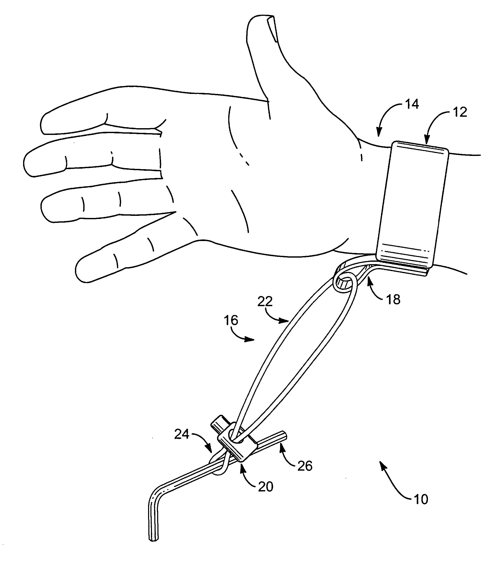
[0033] Referring to FIG. 1, in selected embodiments a tether 10 in accordance with the present invention may include a band 12 sized and shaped to engage some portion of a user's hand, forearm, upper arm, belt, tool belt, clothing, or the like. For example, in certain embodiments, a band 12 may be sized and shaped to encircle on...


PUM


Abstract

A tether for securing a variety of instruments. The tether may include a band sized to fit a human wrist, a lanyard formed as a continuous, closed loop, an interface connecting the lanyard to the band, and a lock. The lock may adjustably pinch the lanyard to form two sub-loops therefrom. By adjusting the location where the lock pinches the lanyard, the size of one sub-loop may be continuously increased or decreased, while the size of the other sub-loop may be simultaneously, continuously, and respectively decreased or increased. Accordingly, by adjusting the location where the lock pinches the lanyard, the size of the one sub-loop may continuously vary between a minimum size and a maximum size. In one embodiment, this minimum size may corresponding to an interior diameter within the one sub-loop of substantially zero.

Description

BACKGROUND [0001] 1. The Field of the Invention [0002] This invention relates to object retention systems and, more particularly, to novel systems and methods for tethering to a user instruments such as tools, fasteners, and the like. [0003] 2. The Background Art [0004] In many situations, it is inconvenient, costly, or dangerous to drop an instrument (e.g., a tool, fastener, or the like) during use. For example, in the printing business it is often necessary to work on printing machinery that is in use. If a technician, while perform repairs or effecting adjustments, were to in advertently drop an instrument into such machinery, the typical solution would require the entire printing line to be stopped while someone retrieved the instrument. Such a solution is certainly inconvenient. It is also costly, as production time would be wasted. Moreover, depending on where the instrument were to fail, it may enter and damage moving mechanisms, resulting in repair cost as well as additional...

Claims


Application Information

Patent Timeline
IPC IPC(8): A45F5/00A44C5/00
CPCA45C13/30Y10T24/1368A45F2005/008A45F3/14
Inventor GRIFFITH, GRANT L.GRIFFITH, CARL R.
Owner C & G PROD
Why Eureka
Try Eureka