RFID tag with improved range

Active Publication Date: 2007-05-03
MAGNEX
View PDF2 Cites 55 Cited by
  • Summary
  • Abstract
  • Description
  • Claims
  • Application Information

AI Technical Summary

Benefits of technology

[0013] The invention comprises a method and system for providing an RFID tag

Problems solved by technology

Many more applications of this technology are theoretically possible, but practical implementations have been limited in the past by size and cost constraints.
While the process of constructing ID tag 10 appears simple and straightforward, in practice the process is actually quite difficult to perform with a high degree of repeatable accuracy.
As the physical size of the rfid chip is reduced, these difficulties in assembling a properly functioning ID tag, and the assembly cost, increase accordingly.
While the “coil-on-a-chip” solution does eliminate the problems associated with bonding of discrete components in the ID tag assembly process, it introduces a severe limitation on the effective operating range of an ID tag fabricated according to this technique.
Since the “coil-on-a-chip” ID tags are fabricated usin

Method used


Image

  • RFID tag with improved range
  • RFID tag with improved range
  • RFID tag with improved range

Examples


first embodiment

[0036]FIG. 4 illustrates the invention having a single passive antenna circuit 40. As seen in this Fig., passive antenna circuit 40 comprises a multi-turn coil 42 coupled at each end to different plates of a tuning capacitor 44. Coil 42 has an open central portion sufficiently large to accommodate an RFID tag, such as tag 30. Coil 42 may be formed in any desired fashion, such as the silver paste printing or copper deposition techniques noted above. Capacitor 44 may be a discrete component element or an element formed using semiconductor fabrication techniques (deposition, masking, etching, etc.). The value of capacitor 44 must be carefully chosen so that the resonant frequency of passive antenna circuit 40 matches the operating frequency of RFID tag 30. RFID tag 30, antenna 42 and capacitor 44 are preferably mounted on some type of common mounting surface (not shown), which is usually a mounting substrate fabricated from any suitable material. For example, if the FIG. 4 embodiment i...

second embodiment

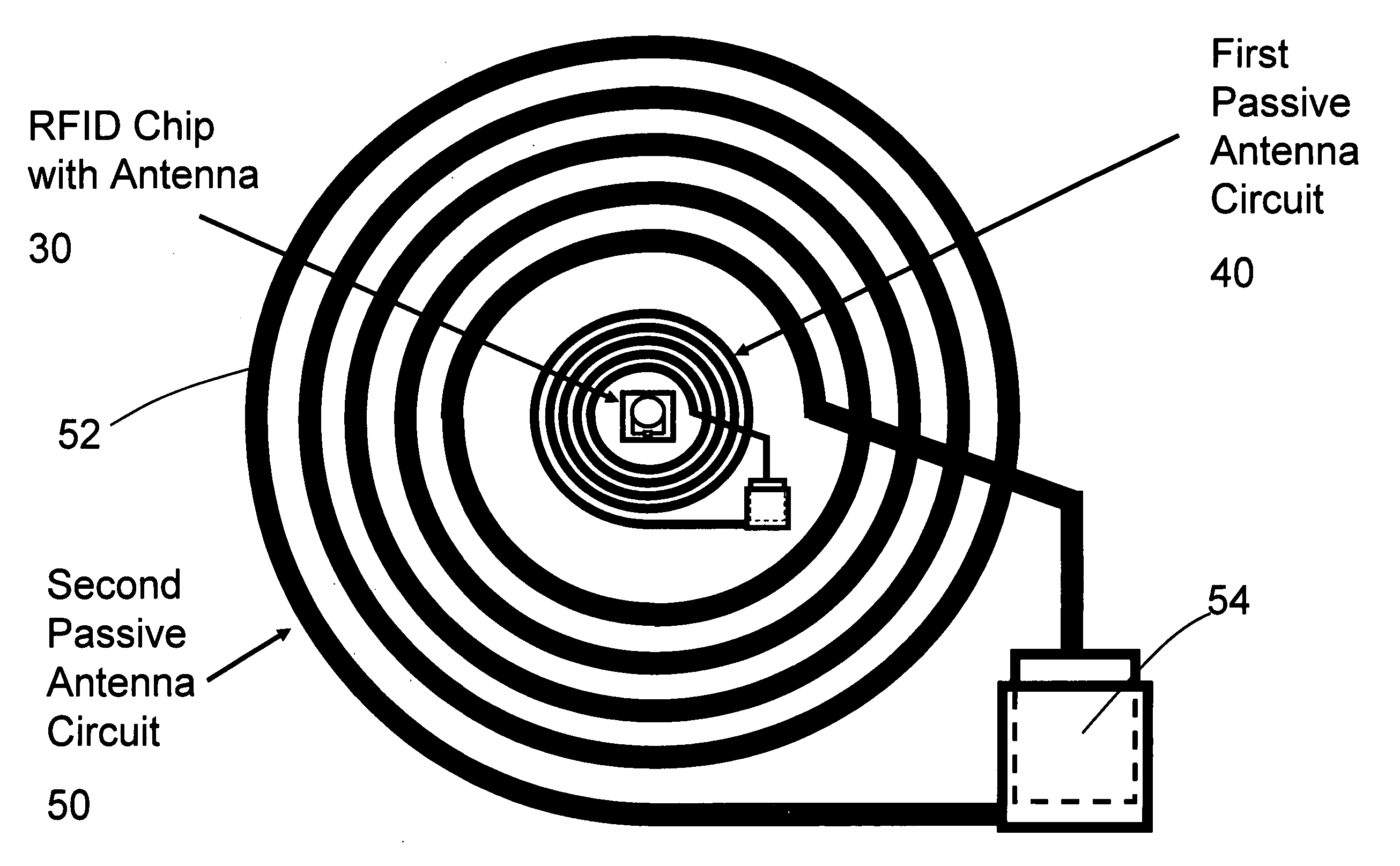
[0038]FIG. 5 illustrates the invention having two passive antenna circuits. As seen in this Fig., first passive antenna circuit 40 is arranged in an attitude surrounding RFID tag 30 in the same manner depicted in FIG. 4. A second larger passive antenna circuit 50 has a relatively large inductive coil 52 ohmically connected at each end to the plates of a second capacitor 54. The central opening in coil 52 is sufficiently large to accommodate coil 42 of first passive antenna circuit 40. Passive antenna circuit 50 is tuned to the same frequency as first passive antenna circuit 40 by selecting a capacitor 54 of proper value. The structure of antenna 52 and capacitor 54 is essentially the same as coil 42 and capacitor 44, with the exception that the dimensions of coil 52 are substantially larger than those of coil 42.

[0039] Operation of the embodiment of FIG. 5 is similar to that already described for the embodiment of FIG. 4. When an interrogation signal at the operating frequency selec...


PUM


Abstract

An RFID tag having an rfid integrated circuit and an antenna is combined with a first passive antenna circuit to provide an extended operating range. The first passive antenna circuit has a first coil and a first capacitor to tune the passive antenna circuit to a resonant frequency the same as the operating frequency of the RFID tag. The first coil has a central opening larger than the size of the antenna. The passive antenna circuit is arranged with the antenna located in the central opening of the coil, preferably in a co-planar manner, to promote inductive interaction therebetween. A second passive antenna circuit essentially identical to the first, but having larger dimensions, is positioned with the coil of the second passive antenna circuit surrounding the first coil to extend the operating range even further.

Description

BACKGROUND OF THE INVENTION [0001] This invention relates to the field of rfid (radio frequency identification) chip and antenna technology. More particularly, this invention relates to an rfid chip and antenna having an improved range of communication with an associated r.f. interrogation / reading device [0002] A typical rfid chip and antenna are usually both incorporated into an ID tag, such as that shown and described in U.S. Pat. No. 6,154,137 issued Nov. 28, 2000, the disclosure of which is hereby incorporated by reference. Generally, an ID tag has the antenna and the rfid chip mounted on or encapsulated in a thin substrate, such as a polyethylene terephthalate (PET) substrate as disclosed in U.S. Pat. No. 6,373,708 B1 issued Apr. 16, 2002, the disclosure of which is hereby incorporated by reference. The antenna is usually a small loop antenna or a dipole antenna, and must be ohmically connected to the rfid chip. The usual loop antenna is a multi-turn planar ohmic conductor form...

Claims


Application Information

Patent Timeline
IPC IPC(8): G06K19/06
CPCG06K19/07749G06K19/07756G06K19/07767
Inventor ZHU, SHENGBOHUANG, SU SHIONG
Owner MAGNEX
Why Eureka
Try Eureka