Mechanical face seal stop pin

a technology of mechanical face and stop pin, which is applied in the direction of engine seals, gas turbine plants, machines/engines, etc., can solve the problems of limited motion range of seal members, and achieve the effect of reducing friction and wear

Active Publication Date: 2007-05-03
RAYTHEON TECH CORP
View PDF18 Cites 25 Cited by
  • Summary
  • Abstract
  • Description
  • Claims
  • Application Information

AI Technical Summary

Benefits of technology

[0006] A gas turbine engine mechanical face seal arrangement according to the present invention includes a seal member having an annular seal element for sealing against a rotatable seal surface. The seal member includes guide slots that cooperate with a guide member to establish a direction of seal member movement. The guide member includes stops to establish a range of movement of the seal member along the direction of seal member movement. The limited range of motion of the seal member protects a bias spring from being over-compressed or over-stressed.
[0007] One exemplary gas turbine

Problems solved by technology

The limited range of motion of the seal member protects a

Method used


Image

  • Mechanical face seal stop pin
  • Mechanical face seal stop pin
  • Mechanical face seal stop pin

Examples


Embodiment Construction

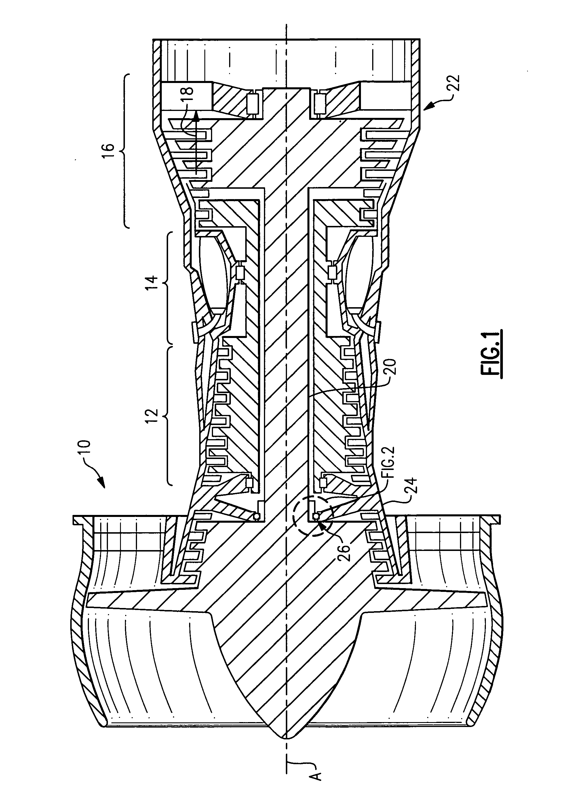
[0016]FIG. 1 illustrates selected portions of an example rotational assembly 10, such as a gas turbine engine for an aircraft. In this example, the rotational assembly 10 includes a compressor section 12, a combustor section 14, and a turbine section 16. The rotational assembly 10 operates in a known manner, feeding compressed air from the compressor section 12 to the combustor section 14. The compressed air is mixed with fuel and reacts to produce a flow of hot gases 18. The turbine section 16 transforms the flow of hot gases 18 into mechanical energy to rotationally drive a shaft 20, such as a turbine engine main shaft. The shaft 20 is coupled with the turbine section 16 and the compressor section 12 such that the turbine section 16 drives the compressor section 12. An exhaust nozzle 22 directs the hot gases 18 out of the rotational assembly 10. An annular, non-rotatable case 24 provides support for the shaft 20 on a bearing arrangement 26, such as a No. 1 bearing.
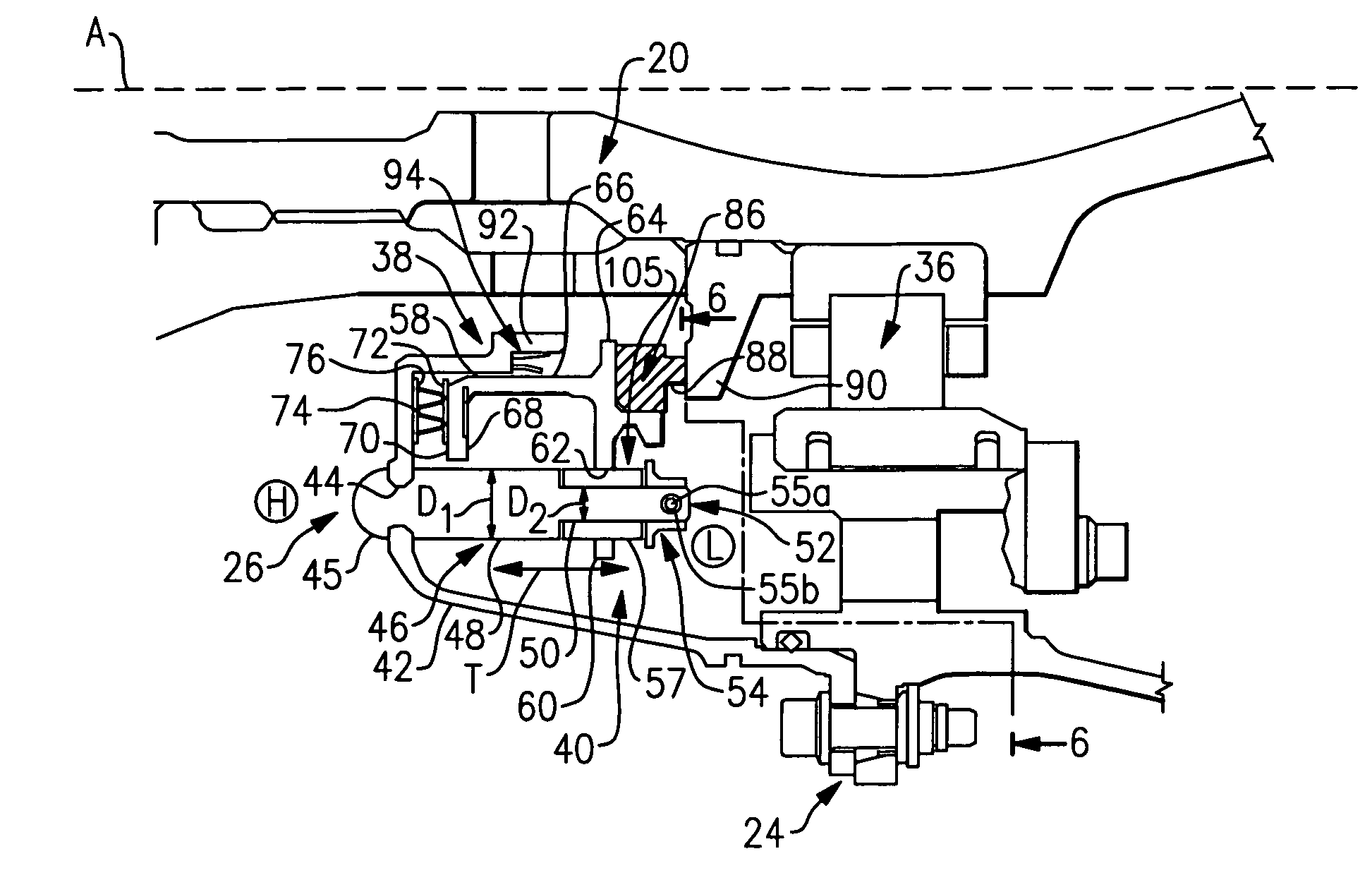
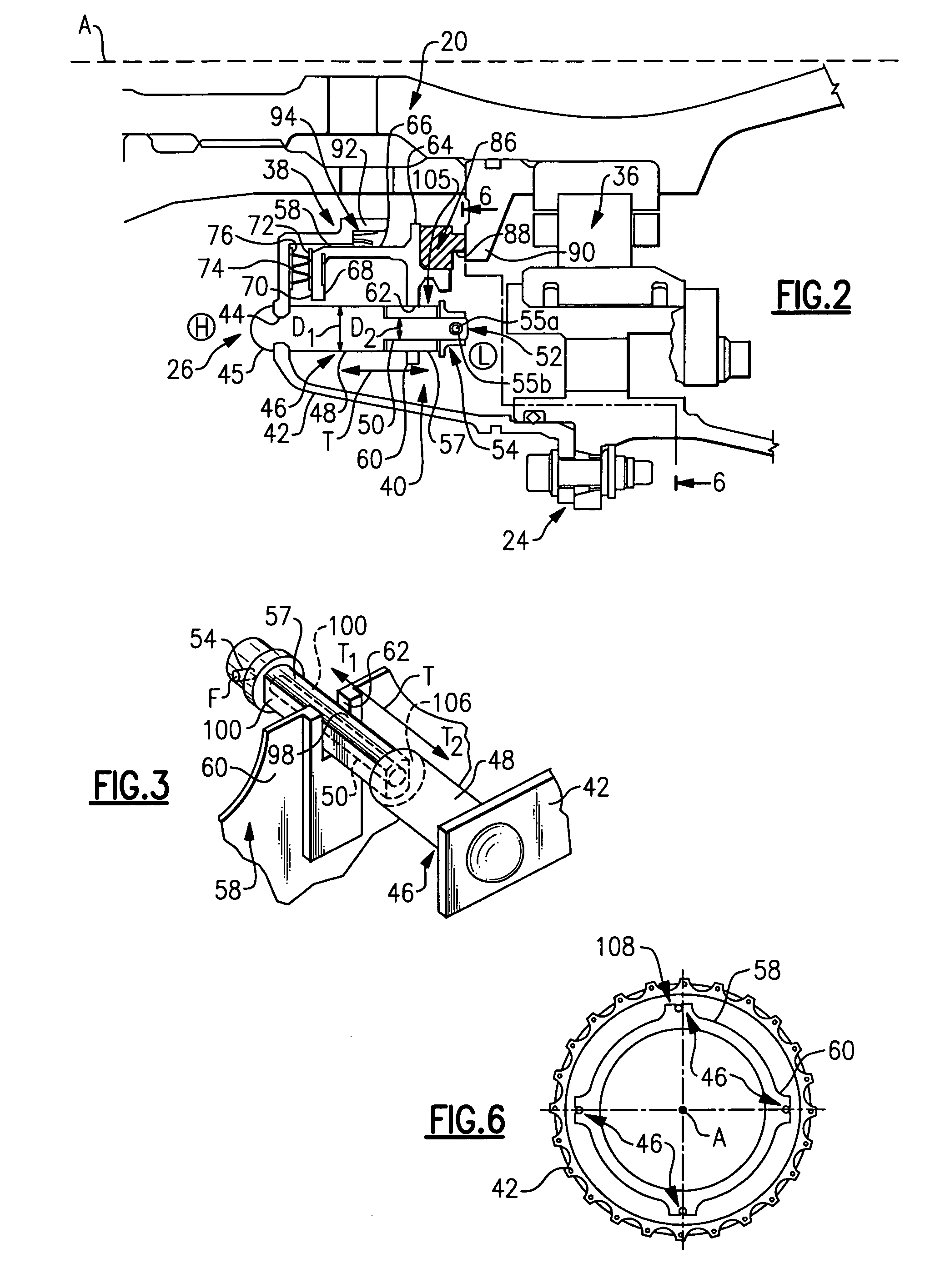
[0017]FIG. 2 sh...


PUM


Abstract

A mechanical face seal arrangement includes a seal member having an annular seal element for sealing against a rotatable seal surface. The seal member includes guide slots that cooperate with the guide member to establish a direction of seal member movement. The guide member includes stops to establish a range of movement of the seal member along the direction of seal member movement.

Description

BACKGROUND OF THE INVENTION [0001] This invention relates to mechanical face seals and, more particularly, to an arrangement and method for establishing a range of movement of a mechanical face seal. [0002] Conventional mechanical face seals are used in rotating equipment, such as gas turbine engines, to provide a seal between regions of high and low fluid pressure and temperature. For example, mechanical face seals are used for sealing a rotating shaft on a pump, compressor, agitator, gas turbine, or other rotating equipment. In gas turbine engines, mechanical face seals are used to prevent hot, high pressure air from entering a bearing compartment that operates at a lower pressure and temperature. [0003] A conventional metal-backed face seal arrangement for a gas turbine engine includes an annular graphitic carbon ring secured to a rotationally static, axially translatable, annular metal seal housing. A seal seat is affixed to a rotatable engine main shaft and positioned axially a...

Claims


Application Information

Patent Timeline
IPC IPC(8): F16J15/34
CPCF01D11/00F02C7/28F05B2260/301F16J15/3464F05D2260/30
Inventor MILLER, JONATHAN L.WOLENSKY, STEPHEN P.
Owner RAYTHEON TECH CORP
Why Eureka
Try Eureka