Moving magnet type linear magnet

a linear magnet and moving magnet technology, applied in the field of linear motors, can solve the problems of increasing guide friction, inconstant thrust, and preventing minute thrust control

Inactive Publication Date: 2007-05-03
YASKAWA DENKI KK
View PDF3 Cites 17 Cited by
  • Summary
  • Abstract
  • Description
  • Claims
  • Application Information

AI Technical Summary

Benefits of technology

[0013] Preferred embodiments of the present invention have been developed in view of the above-mentioned and/or other problems in th

Problems solved by technology

This structure, however, increases the guide friction caused by the magnetic suction force acting on the linear guide.
Furthermore, parallelism errors of the

Method used


Image

  • Moving magnet type linear magnet
  • Moving magnet type linear magnet
  • Moving magnet type linear magnet

Examples


first embodiment

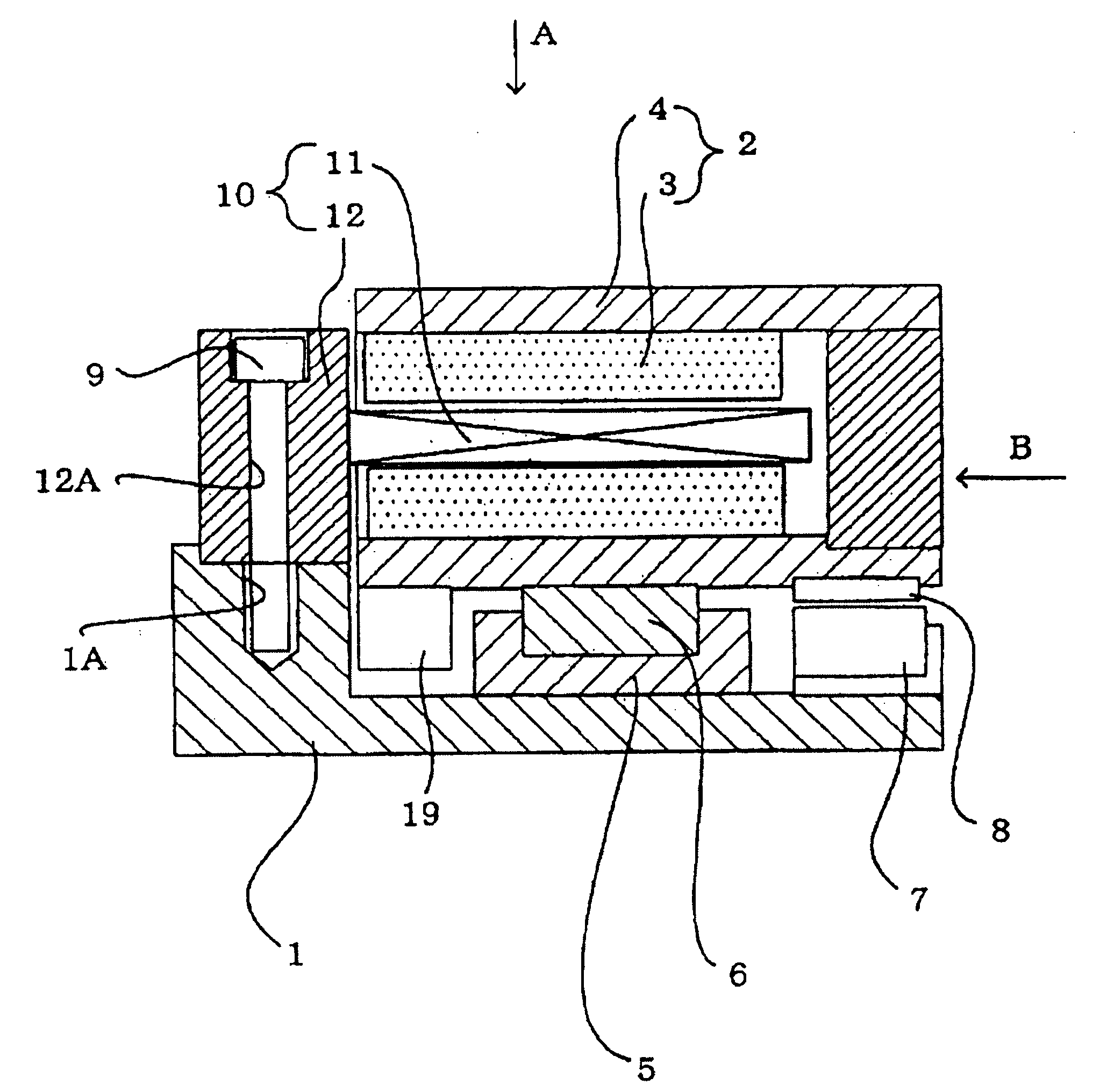
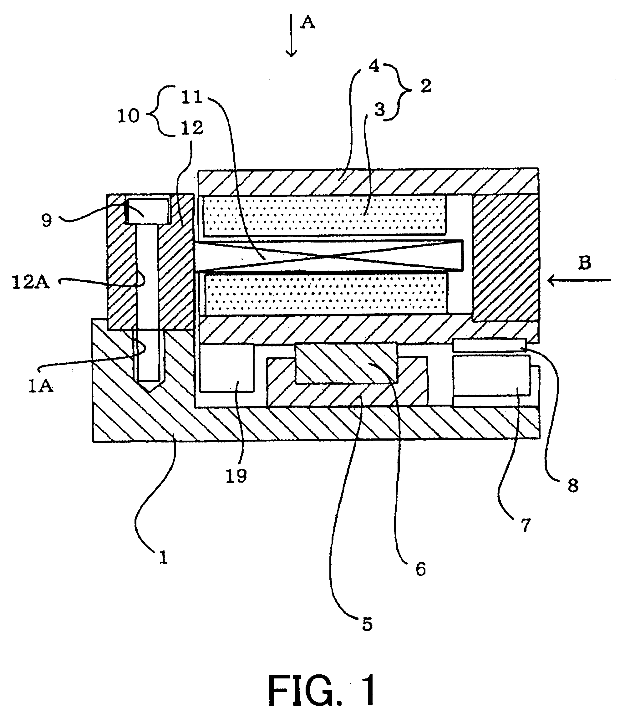
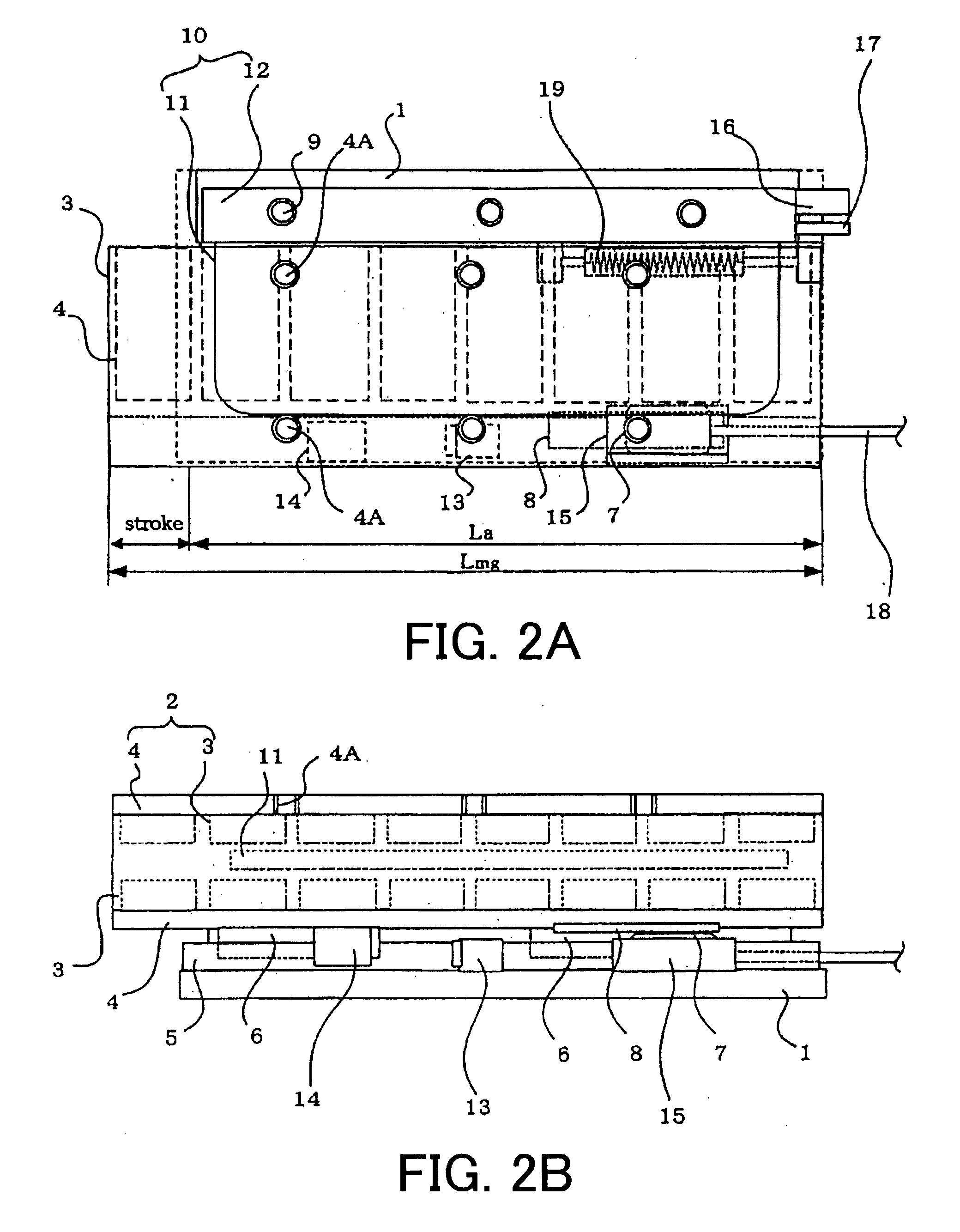
[0055] This embodiment differs from the first embodiment in that a stroke direction length Lmg of the magnet track 2 is set to be shorter than a stroke direction length La of the armature 10 and that the difference La−Lmg between the stroke direction length of the magnet track 2 and that of the armature 10 defines an effective stroke length. Furthermore, in this embodiment, the initial magnetic pole detection of the linear slider is performed by software. In the meantime, initial magnetic pole detection of the linear slider requires a magnetic pole search by software at the time of turning on the power supply.

[0056] Accordingly, in this embodiment, the coreless armature length is set to be shorter than the magnet track length and the length difference defines the effective stroke of the linear slider. Therefore, the drive stroke can be secured within the entire length of the fixed base 1, resulting in a compact linear slider.

[0057] The other structure of this embodiment is the same...

second embodiment

[0060] In this embodiment, since the stroke direction length Lmg of the magnet track 2 is set to be longer than the stroke direction length La of the armature 10 and that the magnetic pole detector formed separately from the armature 10 is arranged beside the end of the armature 10, even in cases where the movable unit moves the full stroke length, the initial magnetic pole detection can be consistently performed by the magnetic pole detector. This eliminates the needs of magnetic pole detection by software at the time of turning on the electric power which is required in the

[0061] The other structure of this second embodiment is the same as that of the first embodiment. Accordingly, the cumulative explanation will be omitted by allotting the same reference numeral as in the first embodiment to the corresponding portion of this third embodiment.

[0062] According to the present invention, minute thrust control can be performed by decreasing the linear guide friction and making the fr...


PUM


Abstract

In some embodiments, a moving magnet type linear slider capable of eliminating a magnet suction force caused by a linear motor to minimize the linear guide friction is provided. The field of the linear motor includes magnet track having a horizontally arranged generally U-shaped magnetic yoke and plural pairs of field permanent magnets arranged on inner opposed surfaces of the magnetic yoke with polarities arranged alternately in a longitudinal direction of the magnetic yoke, each pair of the filed permanent magnets being arranged with opposite polarities faced with each other. The armature of the linear motor includes an armature holder mounted on the side portion of the fixed base in a vertically extended manner, and a planar coreless armature holder horizontally held by the armature holder. The stroke direction length Lmg of the magnet track is set to be longer than the stroke direction length La of the armature. Furthermore, a gravity compensation spring for compensating the weight of the movable unit is provided at the bottom portion of the magnet track so as to face the fixed base.

Description

[0001] This application is a continuation-in-part of International Patent Application No. PCT / JP2005 / 008678 filed on May 12, 2005. This application claims priority under 35 U.S.C. §119 to Japanese Patent Application No. 2004-175306 filed on Jun. 14, 2004. Each of the entire disclosures of these applications is incorporated herein by reference in its entirety.BACKGROUND OF THE INVENTION [0002] 1. Field of the Invention [0003] The present invention relates to a linear motor for use in various industrial machinery, such as, e.g., electrical component mounting apparatuses, semiconductor related apparatuses, or machine tools, and suitably used for driving the direct acting mechanism thereof, and more specifically to a moving magnet type linear slider equipped with a magnetic field system having permanent magnets as a moving unit and an armature having an armature winding as a stator. [0004] 2. Description of Related Art [0005] The following description sets forth the inventor's knowledge...

Claims


Application Information

Patent Timeline
IPC IPC(8): H02K41/00H02K7/00H02K41/02H02K41/03
CPCH02K7/00H02K41/03H02K41/02
Inventor MIYAMOTO, YASUHIROKOBA, TATSUHIKO
Owner YASKAWA DENKI KK
Why Eureka
Try Eureka