Axial bearing for use in a hydraulic device, a hydraulic transformer and a vehicle with a hydraulic drive system

a technology of axial bearing and hydraulic device, which is applied in the direction of fluid hybrid vehicles, gearing control, engines with rotating cylinders, etc., can solve the problems of difficult to optimize the axial bearing, models that do not describe the situation properly, and the pressure profile of the gap is often unpredictable, so as to prevent undesired or unexpected rotation of the wheels

Active Publication Date: 2014-03-25
INNAS
View PDF16 Cites 0 Cited by
  • Summary
  • Abstract
  • Description
  • Claims
  • Application Information

AI Technical Summary

Benefits of technology

[0008]In order to reduce the disadvantages the axial bearing, the circular or arc-shaped ridge and the bearing surface comprise a ridge chamber for locally creating a larger adjustable gap between the circular or arc-shaped ridge and the bearing surface. Because of this feature, the pressure profile in the adjustable gap is more stable as the pressure in the ridge chamber is constant. The pressure changes from the one side of the circular of arc-shaped ridge to the other side take place over a considerably reduced distance so that variations in the pressure profile have less influence on the force counteracting the axial load and have less influence on the gap-height. A further result is that over a considerable surface of the adjustable gap the gap-height is higher which strongly reduces the viscous friction in the adjustable gap. In situations where the walls of the adjustable gap have a high relative speed, locally increasing the gap-height strongly reduces the friction and heat generation. This leads to less energy loss and less deformation due to local high temperatures in the walls of the adjustable gap on the circular or arc-shaped ridge and the bearing surface. This reduces the risk of metallic contact and so reduces wear.
[0009]In an embodiment, the ridge chamber has a surface that is at least 50% of the surface of the circular or arc shaped ridge. This ensures that for at least half the surface the friction between rotating parts is considerably reduced, which means that there is a considerable reduction or possibly halving of the viscous friction between the two parts.
[0010]In an embodiment, the ridge chamber has a depth of more than 10-30 microns. This ensures that in the ridge chamber there is sufficient oil of a constant pressure. In this way oil pressure in the ridge chamber counteracts the axial load with a constant force that is little influenced by the gap-height.

Problems solved by technology

As the gap-height is small, from 2 to 15 microns, minor changes in temperature distribution in the walls of the gap create changes in the diverging or converging of the walls so that the pressure profile in the gap often is unpredictable.
The walls of the gap influence the flow in such narrow gaps considerably and the flow theories using laminar or turbulent flow models do not describe the situation properly.
In the known axial bearings, it is very difficult to optimize the axial bearing.
A too small axial load leads to a large height of the adjustable gap due to the oil pressure in the adjustable gap between the circular or arc-shaped ridge and the bearing surface.
This can lead to a too large oil flow through the gap.
If the axial load is too large, there is too much friction during rotation of the rotor combined with heating of the oil flow due to viscous losses in the adjustable gap.
In addition, in an adjustable gap that is very narrow, local deformations or local disturbances in the flow through the gap may occur which might lead to further local heat generation.
Local heat generation leads to deformations of the circular of arc-shaped ridge or the bearing surface and to further narrowing of the gap.
These deformations might lead to undesired wear as metallic contact between the rotating and stationary parts may occur.

Method used


Image

  • Axial bearing for use in a hydraulic device, a hydraulic transformer and a vehicle with a hydraulic drive system
  • Axial bearing for use in a hydraulic device, a hydraulic transformer and a vehicle with a hydraulic drive system
  • Axial bearing for use in a hydraulic device, a hydraulic transformer and a vehicle with a hydraulic drive system

Examples


Embodiment Construction

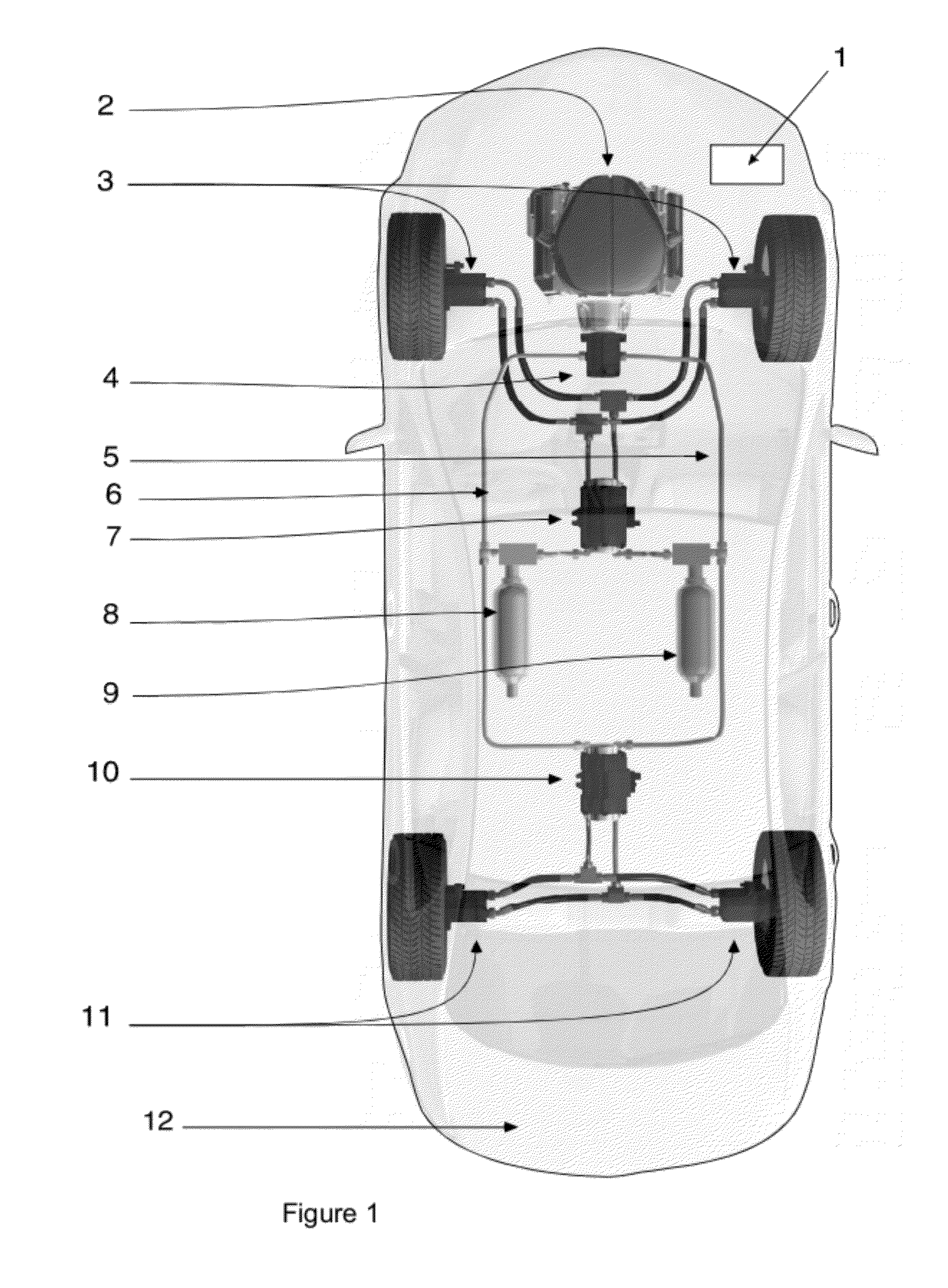
[0041]FIG. 1 shows a passenger car 12 with the various components of a hydraulic drive system for the car wherein all four wheels of the car 12 are driven. The drive system comprises an internal combustion engine 2 that drives a constant displacement pump 4 that pumps hydraulic fluid from a common low-pressure rail 6 to a common high-pressure rail 5. The common low-pressure rail 6 is connected to a low-pressure accumulator 8 and the common high-pressure rail 5 is connected to a high-pressure accumulator 9. A drive control system 1 controls the internal combustion engine 2 and this drive control system 1 maintains by controlling the rotation speed and / or of the starting or stopping of the internal combustion engine 2 that the hydraulic pressure in the common high-pressure rail 5 is between a high and a low value.

[0042]The front wheels of the passenger car 12 each have a front wheel motor / pump 3 that is connected to a front axle hydraulic transformer 7. Document WO97 / 31185 describes t...


PUM


Abstract

An axial bearing between a first part and a second part that presses with an axial load against the first part and can rotate around a rotation axis relative to the first part comprising a circular or arc-shaped ridge on the first part centered around the rotation axis, a pressure source for providing pressurized hydraulic fluid on a first side of the circular or arc-shaped ridge, an adjustable gap between the circular or arc shaped ridge and a bearing surface on the second part, wherein the pressurized hydraulic fluid flows through the adjustable gap to a second side of the circular or arc-shaped ridge. In accordance with the invention the circular or arc-shaped ridge or the bearing surface include a ridge chamber for locally creating a larger adjustable gap between the circular or arc-shaped ridge and the bearing surface.

Description

CROSS-REFERENCE TO RELATED APPLICATIONS[0001]The present application is a continuation of pending International patent application PCT / EP2010 / 054702 filed on Apr. 9, 2010 which designates the United States and claims priority from European Patent applications EP 09161738.1 filed on Jun. 2, 2009 and EP 09158296.5 filed on Apr. 20, 2009. The content of all prior applications is incorporated herein by reference.FIELD OF THE INVENTION[0002]The invention concerns an axial bearing between a first part and a second part that presses with an axial load against the first part and can rotate around a rotation axis relative to the first part comprising a circular or arc-shaped ridge on the first part centered around the rotation axis, a pressure source for providing pressurized hydraulic fluid on a first side of the circular or arc-shaped ridge, an adjustable gap between the circular or arc shaped ridge and a bearing surface on the second part, wherein the pressurized hydraulic fluid flows thr...

Claims


Application Information

Patent Timeline
Patent Type & Authority Patents(United States)
IPC IPC(8): F16C17/00F16C32/06
CPCF16C32/0659F04B1/2021F04B1/2071F16C32/0629F15B3/00F16H61/4096F16H61/448Y02T10/6208B60K6/12F16C32/0692F15B21/14F04B1/24F04B1/2085B60K7/0015B60K17/356F15B11/0445F16C2360/00Y02T10/62
Inventor ACHTEN, PETER, A., J.
Owner INNAS
Why Eureka
Try Eureka