Drainage method for multilayer reservoirs

a reservoir and multi-layer technology, applied in the direction of directional drilling, artificial islands, borehole/well accessories, etc., can solve the problems of increased pressure differences between layers, water conduction and water breakthrough in the wellbore, and the problem of particularly severe problems, to achieve the effect of increasing the drainage surface area

Active Publication Date: 2014-07-15
SCHLUMBERGER TECH CORP
View PDF13 Cites 3 Cited by
  • Summary
  • Abstract
  • Description
  • Claims
  • Application Information

AI Technical Summary

Benefits of technology

[0013]The series of lateral boreholes are preferably selected to minimise pressure differences between the layers of the reservoir.
[0021]Increasing the drainage surface area of the reservoir layer having the lower flow rate, will increase the flow rate of the low flow rate layer, and applying this approach to the various layers flattens the pressure profile of the multilayer reservoir. This can help improve the productivity of the well.
[0027]Any combination of one or more of the above may be used to increase the drainage surface area.

Problems solved by technology

This problem is particularly severe in multilayer reservoirs.
If one layer is depleted faster than the other layers, this can lead to the build up of greater pressure differences between the layers than are initially present.
These pressure differences can cause cross-flows between the layers and the greater pressure gradient formed during production can cause water coning and water breakthrough in the wellbore.
In certain circumstances, no casing is used (barefoot completion) but such completions can be problematic due to the lack of support for the formation and the possibility of borehole collapse, sanding and the like.
Ultimately, the ability of the borehole to produce fluids is limited by the surface area of the borehole in the layer in question.
However, this can often lead to an overall reduction in the rate of production from the borehole.
While such an approach does allow a greater producing surface to be obtained in a given reservoir layer, the problems of pressure differences between layers still occur.

Method used


Image

  • Drainage method for multilayer reservoirs
  • Drainage method for multilayer reservoirs
  • Drainage method for multilayer reservoirs

Examples


example

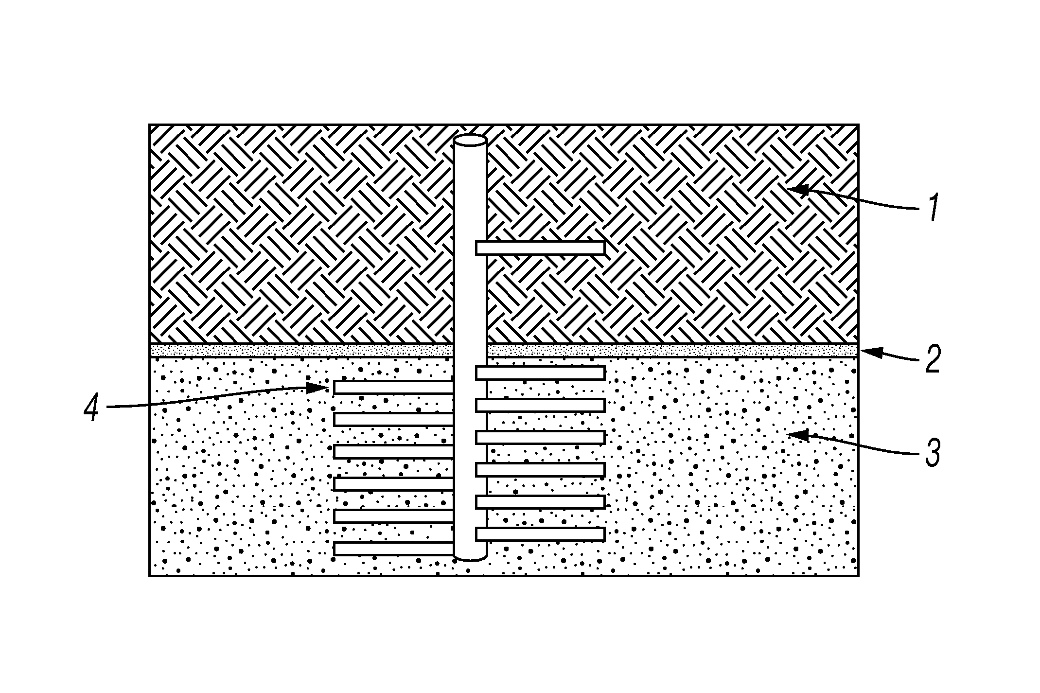
[0046]A multilayer reservoir wellbore is modelled in a Cartesian grid using ECLIPSE (see above). The reservoir model is made of two layers, layer 1 a high mobility layer having a permeability of 100 mD and layer 2 a low mobility layer having a permeability of 10 mD. The layers are separated by a shaly impermeable barrier.

[0047]The field pressure drop and water cut for a standard perforated vertical well and a cased hole with lateral drainholes are compared using the simulation model. The results obtained for the perforated cased hole and the well with lateral drainholes are shown in Table 1. FIG. 4 shows a comparison of the well water cut over time for a perforated cased hole and a well with lateral drainholes obtained using the simulation model.

[0048]

TABLE 1PerforatedLateralcased holedrainholesDaily production1000barrels850barrelsbefore waterbreakthroughWater breakthrough1200days2200daysstarting atWater Cut limit (50%)3300daysNot reached at 20years productionTotal production2,100,0...


PUM


Abstract

A main borehole is drilled into an underground reservoir comprising a plurality of layers of different fluid mobilities. The fluid mobility in each of the plurality of layers is determined. A number of lateral boreholes extending from the main borehole in each of the plurality of layers are then drilled based on the determined fluid mobility in each of the plurality of layers, such that resulting fluid production rates in each of the plurality of layers are substantially similar.

Description

TECHNICAL FIELD[0001]This invention relates to a method of enhancing the production of hydrocarbons from multilayer reservoirs, and in particular is directed to methods for determining a proper arrangement of lateral boreholes to provide an improved drainage surface for reservoirs having layers of different properties.BACKGROUND ART[0002]In oil and gas wells not all the oil and gas in a reservoir can be recovered. This problem is particularly severe in multilayer reservoirs. Using traditional production methods oil and gas may be bypassed due to the cross flows or water coning that occurs as the layers in the reservoirs are depleted.[0003]Production of oil and gas from a reservoir is dependant on the mobility of the fluid in the reservoir. Mobility is effectively the ease with which fluids can be produced from a formation and depends on characteristics such as porosity, permeability and fluid viscosity. In multilayer reservoirs, for a given fluid viscosity, the more permeable layers...

Claims


Application Information

Patent Timeline
Patent Type & Authority Patents(United States)
IPC IPC(8): E21B7/04
CPCE21B43/30E21B43/14E21B43/32E21B49/00
Inventor DEMICHEL, CINDYWOODBURN, CHARLESSAYGI, GOKHANMANIN, YVESBELANI, ASHOKWATFA, MOHAMED
Owner SCHLUMBERGER TECH CORP
Why Eureka
Try Eureka