

Axial Bearing For Use In A Hydraulic Device, A Hydraulic Transformer And A Vehicle With A Hydraulic Drive System
- Summary
- Abstract
- Description
- Claims
- Application Information
AI Technical Summary
Benefits of technology
Problems solved by technology
Method used
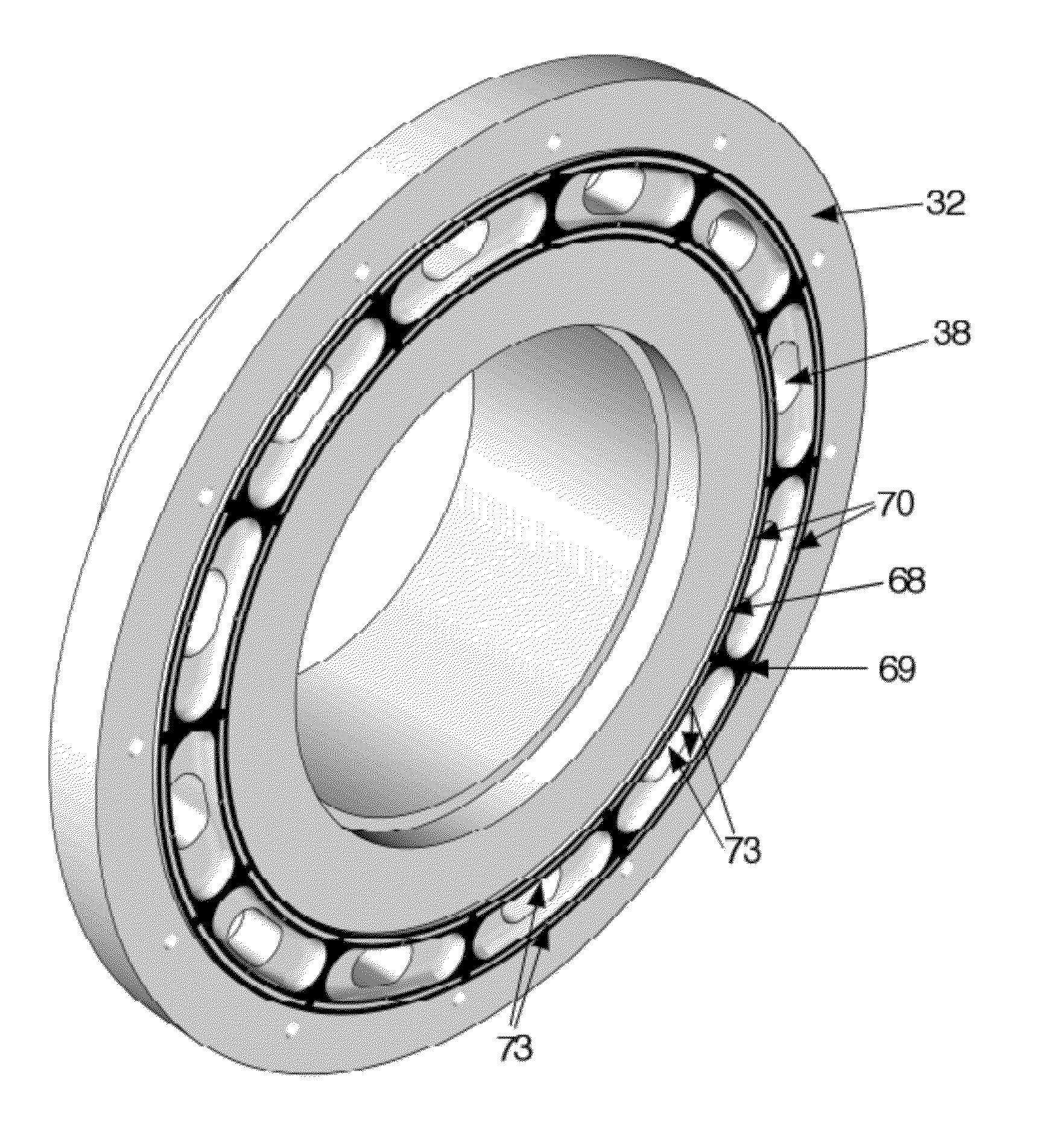
Image

Examples
Embodiment Construction
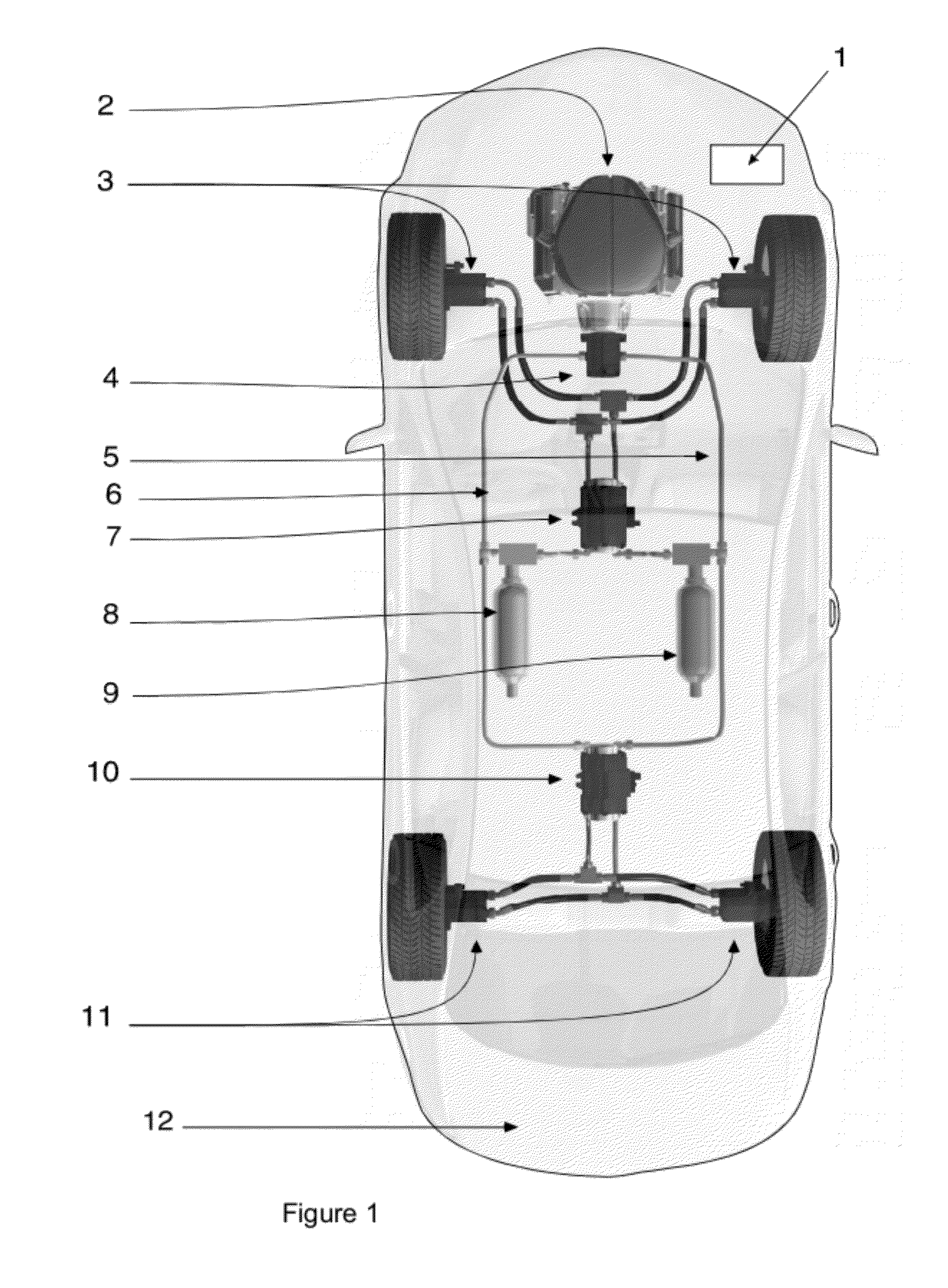
[0041]FIG. 1 shows a passenger car 12 with the various components of a hydraulic drive system for the car wherein all four wheels of the car 12 are driven. The drive system comprises an internal combustion engine 2 that drives a constant displacement pump 4 that pumps hydraulic fluid from a common low-pressure rail 6 to a common high-pressure rail 5. The common low-pressure rail 6 is connected to a low-pressure accumulator 8 and the common high-pressure rail 5 is connected to a high-pressure accumulator 9. A drive control system 1 controls the internal combustion engine 2 and this drive control system 1 maintains by controlling the rotation speed and / or of the starting or stopping of the internal combustion engine 2 that the hydraulic pressure in the common high-pressure rail 5 is between a high and a low value.
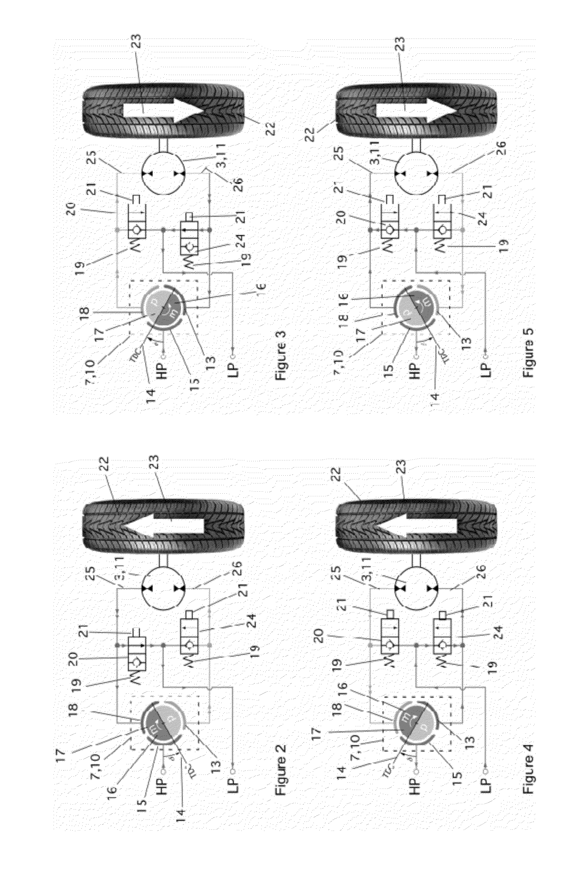
[0042]The front wheels of the passenger car 12 each have a front wheel motor / pump 3 that is connected to a front axle hydraulic transformer 7. Document WO97 / 31185 describes t...
PUM
 Abstract
Description
Claims
Application Information