
Monobloc piston with a low friction skirt

a monobloc piston and low friction technology, applied in the direction of pistons, machines/engines, mechanical equipment, etc., can solve the problems of reducing the useful life of associated components, increasing the overall weight of the piston, and reducing the fuel economy of the engine, so as to improve the guidance of the piston, reduce dynamic viscosity friction, and improve the effect of oil flow

Inactive Publication Date: 2018-03-06
TENNECO INC
View PDF26 Cites 0 Cited by
  • Summary
  • Abstract
  • Description
  • Claims
  • Application Information

AI Technical Summary

Benefits of technology

The present invention can improve the performance and life of engines by improving oil flow, reducing friction, controlling piston movement, reducing oil consumption, and reducing exhaust emissions. The improvements made by this invention can lead to increased fuel efficiency and longer engine life.

Problems solved by technology

Although the skirts are generally effective in guiding the piston within a cylinder bore, they have inherent drawbacks.
First, being constructed as a continuous rectangular wall of material, the skirts increase the overall weight of the piston.
The increased weight can decrease the useful life of associated components by imparting increased inertial forces thereon, while also reducing the fuel economy of the engine.
Further, increased area of the skirts causes friction against the cylinder liner, thereby further reducing the useful life and fuel economy of the engine.
In addition to these drawbacks, having a continuous rectangular skirt wall reduces the flexibility of the pin bosses.
Accordingly, the pin bosses unable to flex with the wrist pin during a stroke of the piston, and thus, increased friction results in the wrist pin joint and pin bores.
Further yet, manufacture of the skirts can prove difficult in that the processes used to form them must provide for precise formation of wall contours and thicknesses over the full skirt area.
Some attempts have been made to reduce the skirt area and weight, including forming skirts with recesses extending from the lower surface upwardly to the pin bore axis, however, these efforts fall short of attaining a maximized reduction in skirt area and weight, and the aforementioned friction issues still remain in large part between the skirt wall and the cylinder bore, and also in the wrist pin joint and pin bore areas.

Method used


Image

  • Monobloc piston with a low friction skirt
  • Monobloc piston with a low friction skirt
  • Monobloc piston with a low friction skirt

Examples


Embodiment Construction

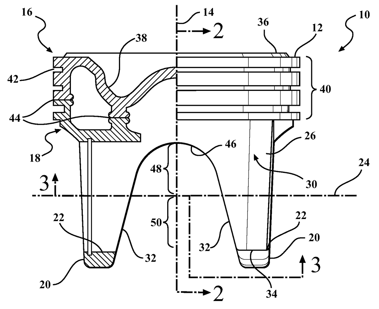
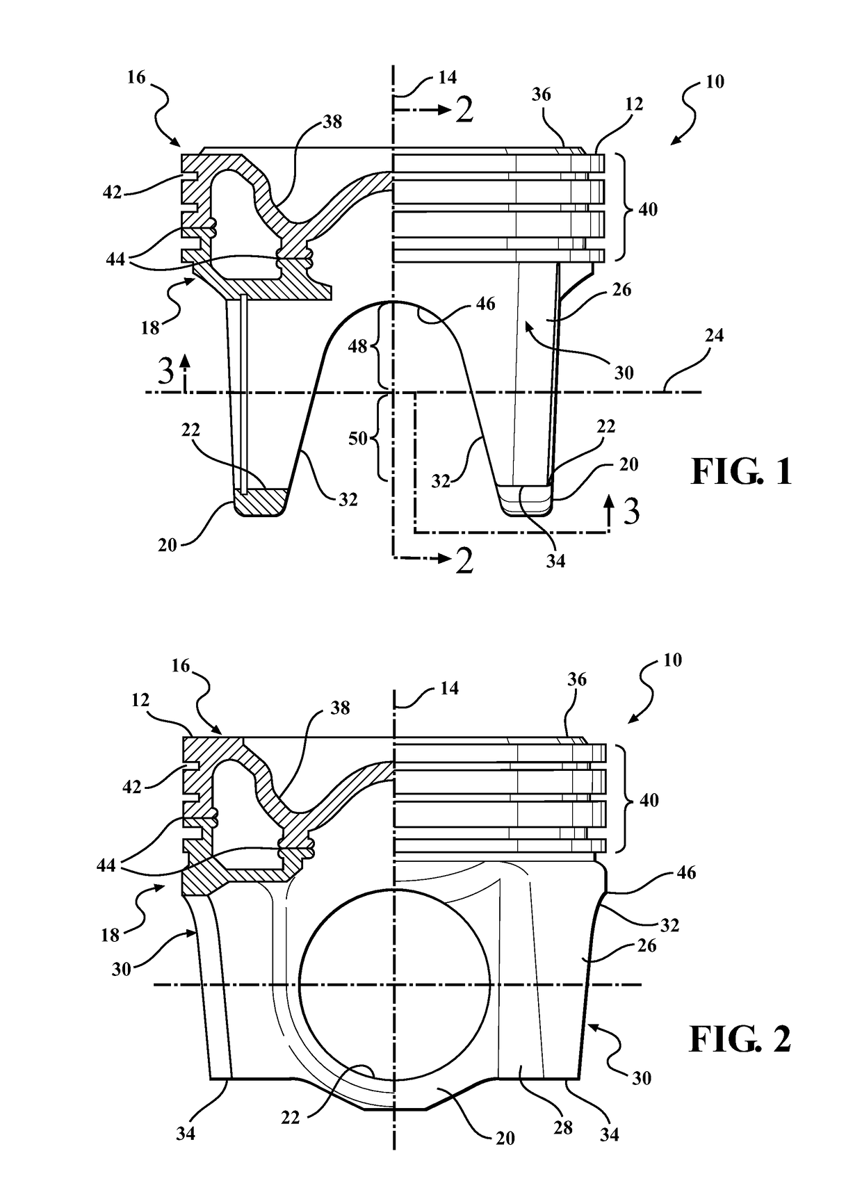
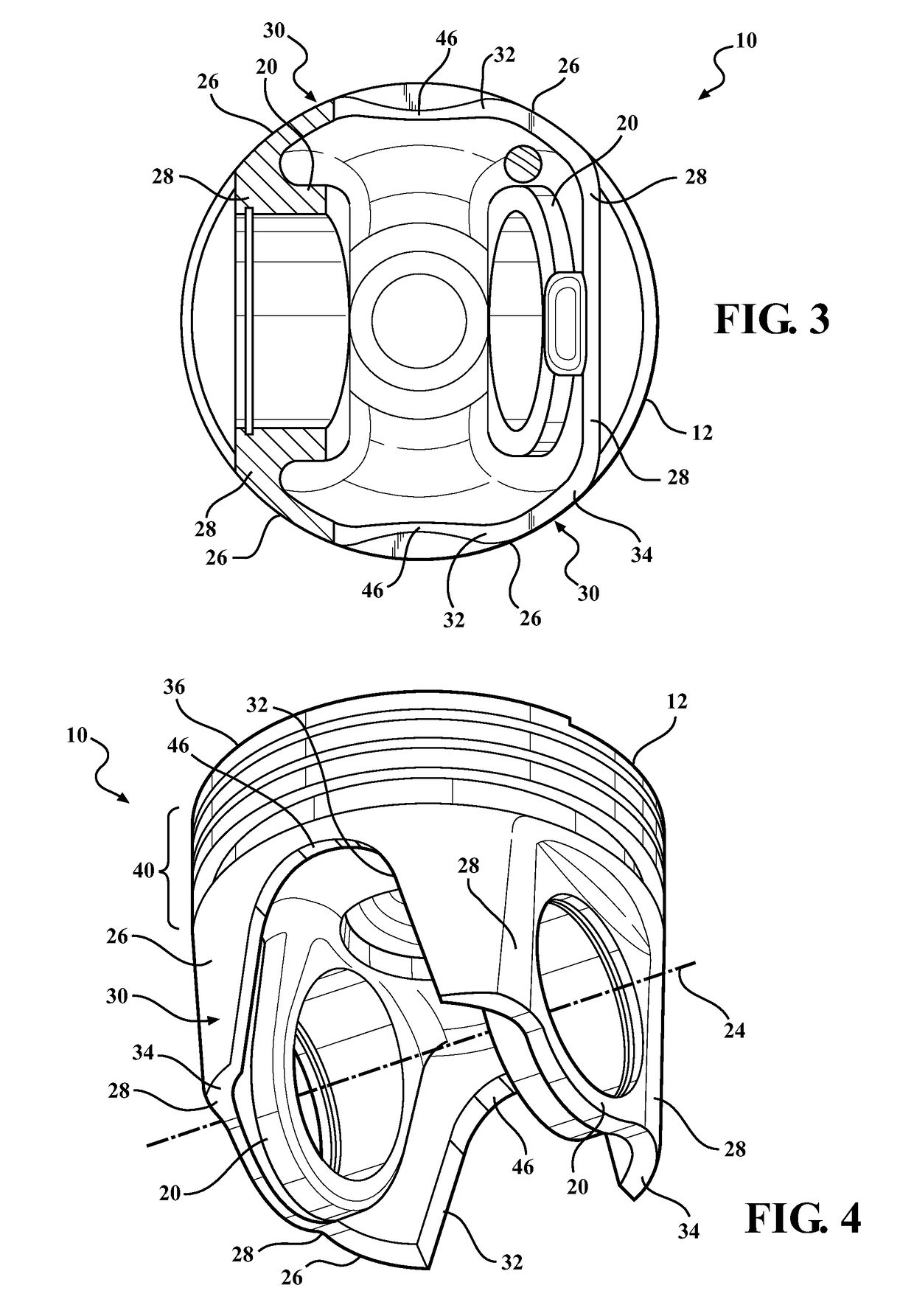
[0020]Referring in more detail to the drawings, FIGS. 1-4 illustrate a piston 10 constructed according to one presently preferred embodiment of the invention for reciprocating movement in a cylinder bore (not shown) of an internal combustion engine, such as a heavy duty diesel engine, for example. The piston 10 has a body 12, either cast or forged, or by any other process of manufacture, extending along a central longitudinal axis 14 along which the piston 10 reciprocates in the cylinder bore. The body 12 is represented, by way of example and without limitation, as having an upper crown 16 joined to a lower crown 18. The lower crown 18 has a pair of pin bosses 20 depending therefrom to provide laterally spaced pin bores 22 aligned along a pin bore axis 24 that extends generally transverse to the central longitudinal axis 14. The pin bosses 20 are joined to laterally spaced skirt portions 26 via strut portions 28. The skirt portions 26 are diametrically spaced from one another across...


PUM


Abstract

A piston for an internal combustion engine has an upper crown portion with a pair of pin bosses depending therefrom, wherein the pin bosses have pin bores axially aligned along a central pin bore axis. A pair of laterally spaced skirt portions are fixedly attached to the pin bosses and depend to a lowermost free edge. At least one of the skirt portions has a recess extending upwardly from the lowermost free edge beyond the central axis of the pin bores.

Description

CROSS-REFERENCE TO RELATED APPLICATIONS[0001]This application claims the benefit of U.S. Provisional Application Ser. No. 61 / 237,472, filed Aug. 27, 2009, which is incorporated herein by reference in its entirety.BACKGROUND OF THE INVENTION[0002]1. Technical Field[0003]This invention relates generally to internal combustion engines, and more particularly to monobloc pistons.[0004]2. Related Art[0005]It is known that internal combustion engines, and particularly diesel engines, utilize monobloc construction pistons having a fixed skirt formed as one piece of material with the piston. The skirts typically have a rectangular configuration extending continuously between opposite pin bosses downwardly to a substantially straight bottom edge. Although the skirts are generally effective in guiding the piston within a cylinder bore, they have inherent drawbacks. First, being constructed as a continuous rectangular wall of material, the skirts increase the overall weight of the piston. The i...

Claims


Application Information

Patent Timeline
Patent Type & Authority Patents(United States)
IPC IPC(8): F02F3/00F02F3/02F02F3/22
CPCF02F3/003F02F3/22F02F3/027
Inventor SCHNEIDER, NORBERT
Owner TENNECO INC
Learn More