Magnetoelectric generator

a generator and magnetoelectric technology, applied in the direction of rotating magnets, synchronous machines with stationary armatures, electrical apparatus, etc., can solve the problems of irregular air gap, deterioration of roundness of flywheels, so as to improve power generation characteristics, improve roundness of bowl-shaped flywheels, and reduce the amount of air gap

Active Publication Date: 2007-05-03
MITSUBISHI ELECTRIC CORP
View PDF3 Cites 9 Cited by
  • Summary
  • Abstract
  • Description
  • Claims
  • Application Information

AI Technical Summary

Benefits of technology

[0012] The present invention aims to solve the above problems and an object of the present invention is to provide a magnetoelectric generator enabling an amount of air gap between permanent magnets and a stator to be made uniform by improving roundness of a bowl-shaped flywheel, thereby enabling reductions in the amount of air gap and improving power generating characteristics, etc.
[0014] The magnetoelectric generator according to the present invention enables an amount of air gap between the permanent magnets and the stator to be made uniform by improving roundness of the bowl-shaped flywheel, thereby enabling reductions in the amount of air gap and improving power generating characteristics, etc.

Problems solved by technology

In the flywheels of conventional magnetoelectric generators, a bar-shaped material is machined into a bowl shape, then press working is applied to form the protruding portions, but roundness of the flywheel deteriorates during this press working, as shown in FIG. 5, giving rise to irregularities in an amount of air gap between the permanent magnets and a stator.
In particular, since flywheels are being made thinner in magnetoelectric generators with a view to reducing size and weight, deterioration in roundness of the flywheel as the protruding portions are being formed on the cylindrical portion by press working has become marked, and due to increases in irregularities in the amount of air gap resulting from press working, problems such as the following have arisen:
A) Fluctuations arise in the rotational locus of the rotating flywheel and adversely affect power generating characteristics (output characteristics);
B) Sliding friction arises between inner peripheral surfaces of the permanent magnets and outer peripheral surfaces of the stator, possibly preventing completion of manufacture; and
C) Temperature differences may also arise in generating coils of the stator due to power generating effects (alternating magnetic field) from increases and decreases in the amount of air gap, reducing service life and reliability of an electrically-insulating coating (a polymeric material) on conducting wires in a portion of the generating coils due to extreme temperature increases.

Method used


Image

  • Magnetoelectric generator
  • Magnetoelectric generator
  • Magnetoelectric generator

Examples


embodiment 1

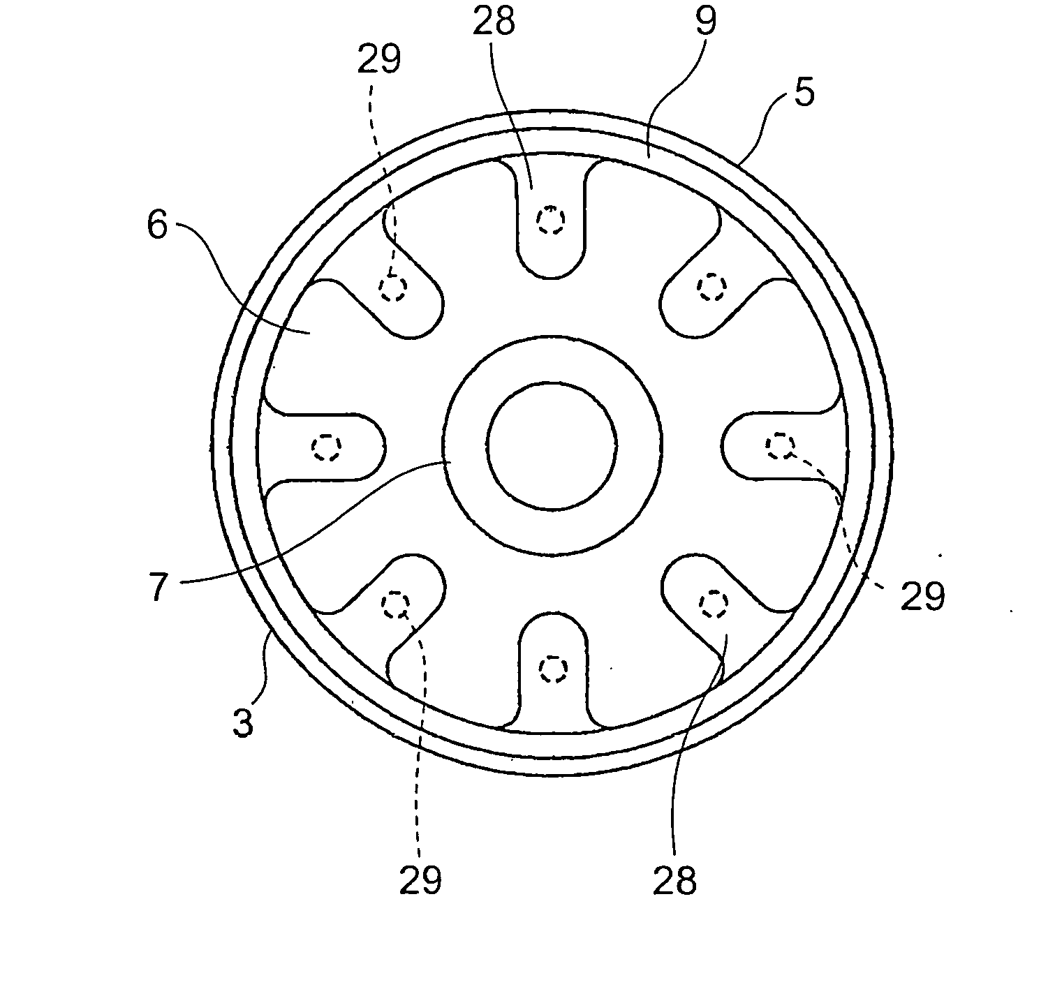
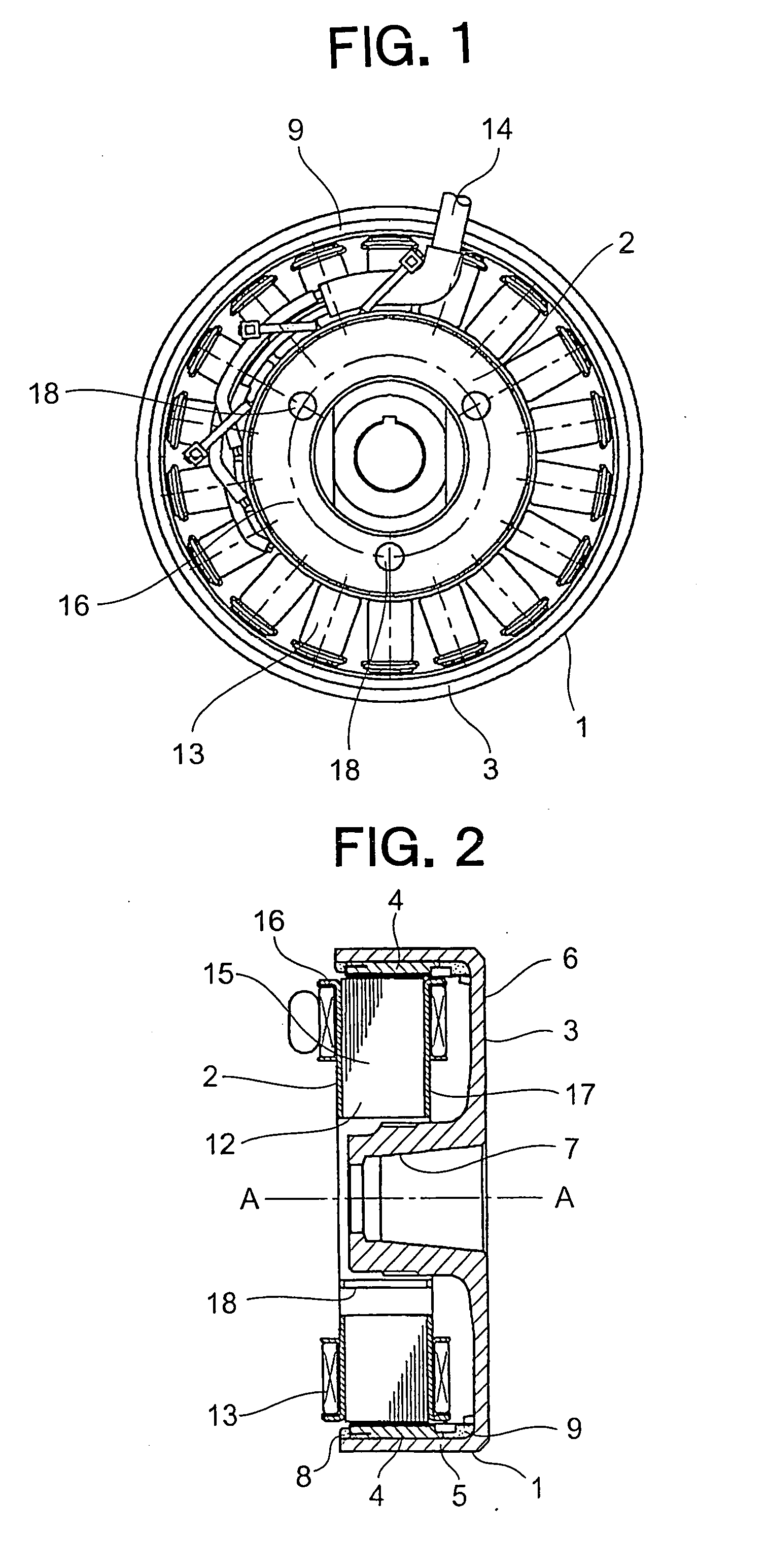
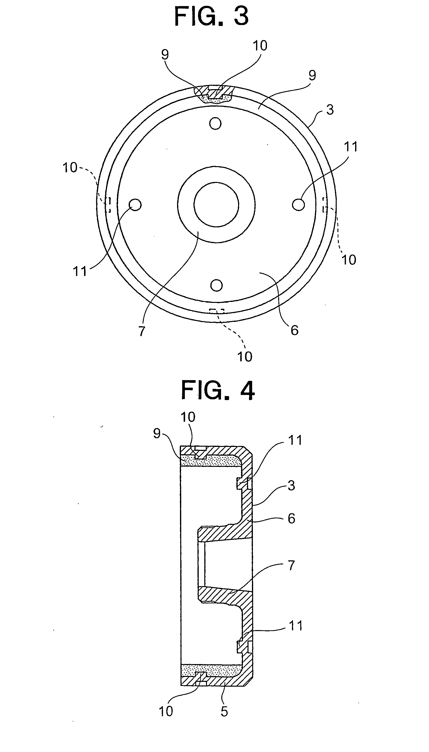
[0031]FIG. 1 is a front elevation showing a magnetoelectric generator according to Embodiment 1 of the present invention, FIG. 2 is a cross section of FIG. 1, FIG. 3 is a front elevation including a cut-away cross section of a portion of a flywheel from FIG. 1, and FIG. 4 is a cross section of FIG. 3.

[0032] This magnetoelectric generator includes: a rotor 1 linked to an internal combustion engine; and a stator 2 mounted to a fixing member (not shown) so as to face the rotor 1.

[0033] The rotor 1 includes: a bowl-shaped flywheel 3; and permanent magnets 4.

[0034] The flywheel 3 is constituted by: a cylindrical portion 5; a boss portion 7; and a bottom portion 6 connecting the boss portion 7 and the cylindrical portion 5. The flywheel 3 rotates around an axis of rotation A-A. The boss portion 7 is fixed to a rotating shaft (not shown) which is driven to rotate by the internal combustion engine.

[0035] Four permanent magnets 4, for example, are fixed to an inner peripheral wall surfac...

embodiment 2

[0053]FIG. 8 is a front elevation including a cut-away cross section of a portion of a flywheel in a magnetoelectric generator according to Embodiment 2, and FIG. 9 is a cross section of the flywheel in FIG. 8.

[0054] In this embodiment, protruding portions 20 constituting retaining portions projecting radially outward are formed by press working from an inner peripheral wall surface of a cylindrical portion 5.

[0055] Press-worked portions 21 for forcibly increasing roundness of a flywheel 3 are formed at four positions at a uniform pitch on a bottom portion 6 in a vicinity of the protruding portions 20 by press working from a surface of the bottom portion 6 on a side near a stator 2.

[0056] The rest of the configuration is similar to that of the magnetoelectric generator according to Embodiment 1, and similar effects to those in Embodiment 1 above can be achieved.

embodiment 3

[0057]FIG. 10 is a front elevation showing a flywheel 3 in a magnetoelectric generator according to Embodiment 3, and FIG. 11 is a cross section of the flywheel 3 in FIG. 10.

[0058] In this embodiment, a plurality of ventilating apertures 22 are formed on a bottom portion 6 of a flywheel 3. Press-worked portions 24 for forcibly increasing roundness of the flywheel 3 are formed between adjacent ventilating apertures 22 by press working from a surface of the bottom portion 6 on an opposite side from the stator 2. Swivel-stopping grooves 25 for preventing a resin material 9 from rotating relative to the flywheel 3 are formed at four positions at a uniform pitch at a peripheral edge portion on a surface of the bottom portion 6 on a side near the stator 2.

[0059] A dislodgment-preventing groove 23 for preventing the resin material 9 from dislodging axially is formed around an entire circumference on an inner peripheral wall surface of a cylindrical portion 5.

[0060] Because the dislodgme...


PUM

PropertyMeasurementUnit
electric poweraaaaaaaaaa
displacementaaaaaaaaaa
shapeaaaaaaaaaa

Abstract

In a magnetoelectric generator generating electric power by electromagnetic induction between permanent magnets and a generating coil due to rotation of a flywheel, a plurality of press-worked portions for forcibly increasing roundness of the flywheel are formed by press working on a bottom portion of the flywheel.

Description

BACKGROUND OF THE INVENTION [0001] 1. Field of the Invention [0002] The present invention relates to a magnetoelectric generator for generating electric power by electromagnetic induction between a permanent magnet and a generating coil due to rotation of a flywheel. [0003] 2. Description of the Related Art [0004] Conventionally, magnetoelectric generators are known in which a plurality of permanent magnets are fixed to an inner peripheral wall surface of a cylindrical portion of a bowl-shaped flywheel so as to be arranged circumferentially, and the permanent magnets are fixed integrally to the flywheel by filling a resin material between adjacent permanent magnets (See Patent Literature 1, for example). [0005] In these magnetoelectric generators, a plurality of protruding-portions projecting inward are formed on the cylindrical portion of the flywheel by press working, and the resin material is engaged by these protruding portions to prevent the resin material and the permanent mag...

Claims


Application Information

Patent Timeline
Patent Type & Authority Applications(United States)
IPC IPC(8): H02K7/02H02K21/12
CPCH02K1/2786Y10T29/49012H02K15/03H02K1/2791
Inventor HASHIBA, MITSUHARU
Owner MITSUBISHI ELECTRIC CORP
Why Eureka
Try Eureka