
Sensor and method of producing sensor

Inactive Publication Date: 2007-05-03
NGK SPARK PLUG CO LTD
View PDF4 Cites 5 Cited by
  • Summary
  • Abstract
  • Description
  • Claims
  • Application Information

AI Technical Summary

Benefits of technology

[0009] The present invention has been made in view of the foregoing problems and has for its object to provide a sensor and a method of producing the same, which is hard to cause breakage of a detection element at the time of assembly with a metallic terminal member and can maintain an electrical connection between an electrode terminal section of the detection element and the metallic terminal member even when the space for disposition of the metallic terminal member is limited.

Problems solved by technology

However, in case a lead frame having a resilient contact portion that exerts an excessively large resilient force is used as in a prior art sensor, a large pressure more than needed is applied from the lead frame to the detection element at the time of assembly of the lead frame and the detection element, so that a damage of the detection element such as chipping or breakage may possibly be caused by that pressure.
Further, since a lead frame large in the width size requires a wide space for disposition thereof, there arises a problem that such a lead frame is not suited for use in a sensor that is needed to be small-sized.
Further, in the event a lead frame large in the width size is used for a detection element formed with a plurality of electrode terminal sections that are small in the width size and positioned close to each other, there is a possibility that one lead frame is brought into contact with all the plurality of electrode terminal sections and a suitable electrical current path cannot be formed.
However, a lead frame having a resilient support portion in a one-point support condition as the above-described prior art lead frame tends to lack a resilient force if formed smaller in the width size, thus being incapable of sufficiently contacting the electrode terminal section due to the lack of resiliency and possibly causing the condition of connection with the electrode terminal section to be unstable.

Method used


Image

  • Sensor and method of producing sensor
  • Sensor and method of producing sensor
  • Sensor and method of producing sensor

Examples


Embodiment Construction

[0042] An embodiment of the present invention will be described hereinafter by reference to drawings.

[0043] In the meantime, according to this embodiment will be described a kind of gas sensor, specifically a wide-range air / fuel ratio sensor 2 (hereinafter also referred to as air / fuel ratio sensor 2) composed of a detection element (gas sensor element) for detecting a particular gas which is an object to be measured and contained in an exhaust gas, for use in an air / fuel ratio feedback control in automotive or other various kinds of internal combustion engines.

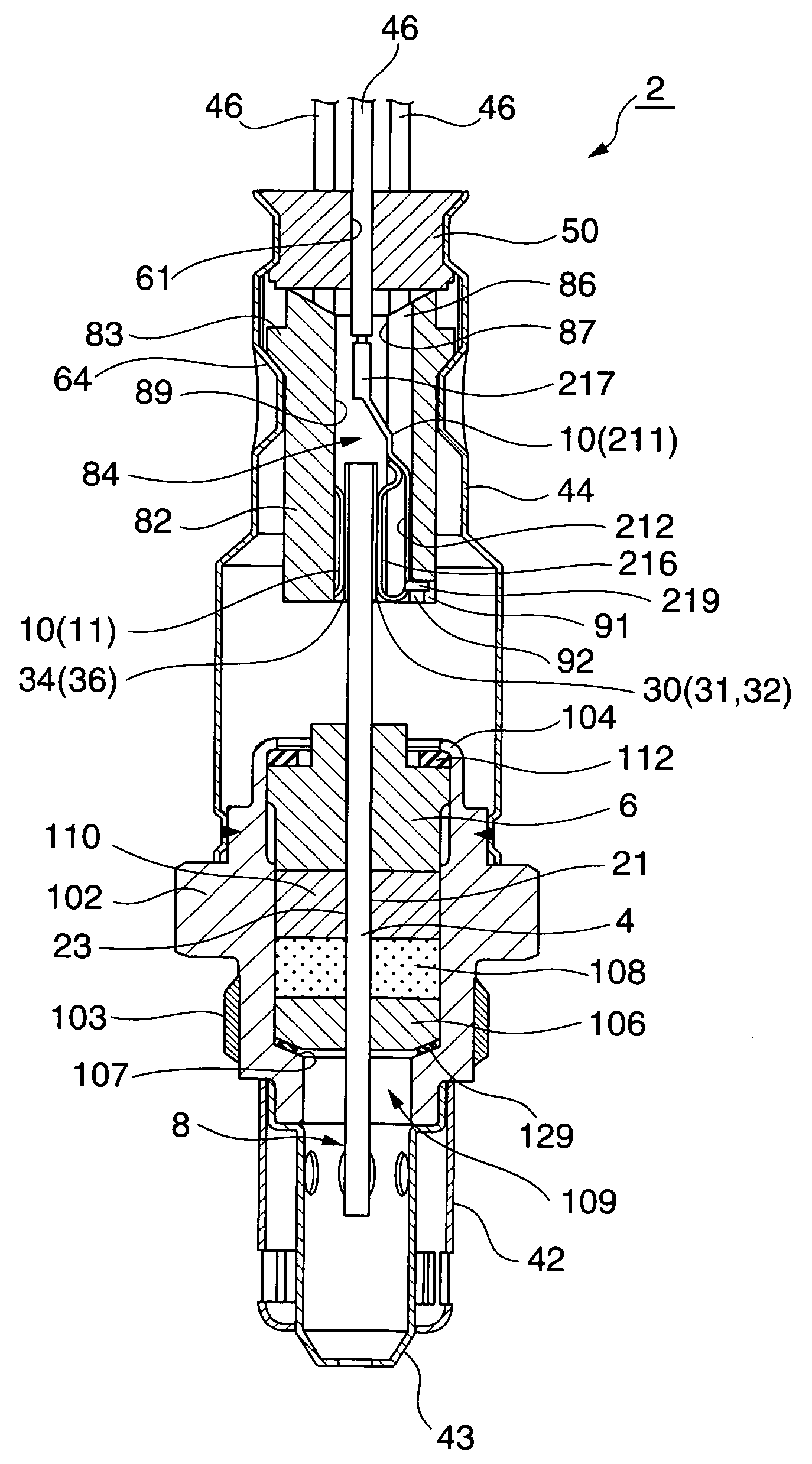
[0044]FIG. 1 is a sectional view showing an overall structure of the air / fuel ratio sensor 2 according to an embodiment of the present invention.

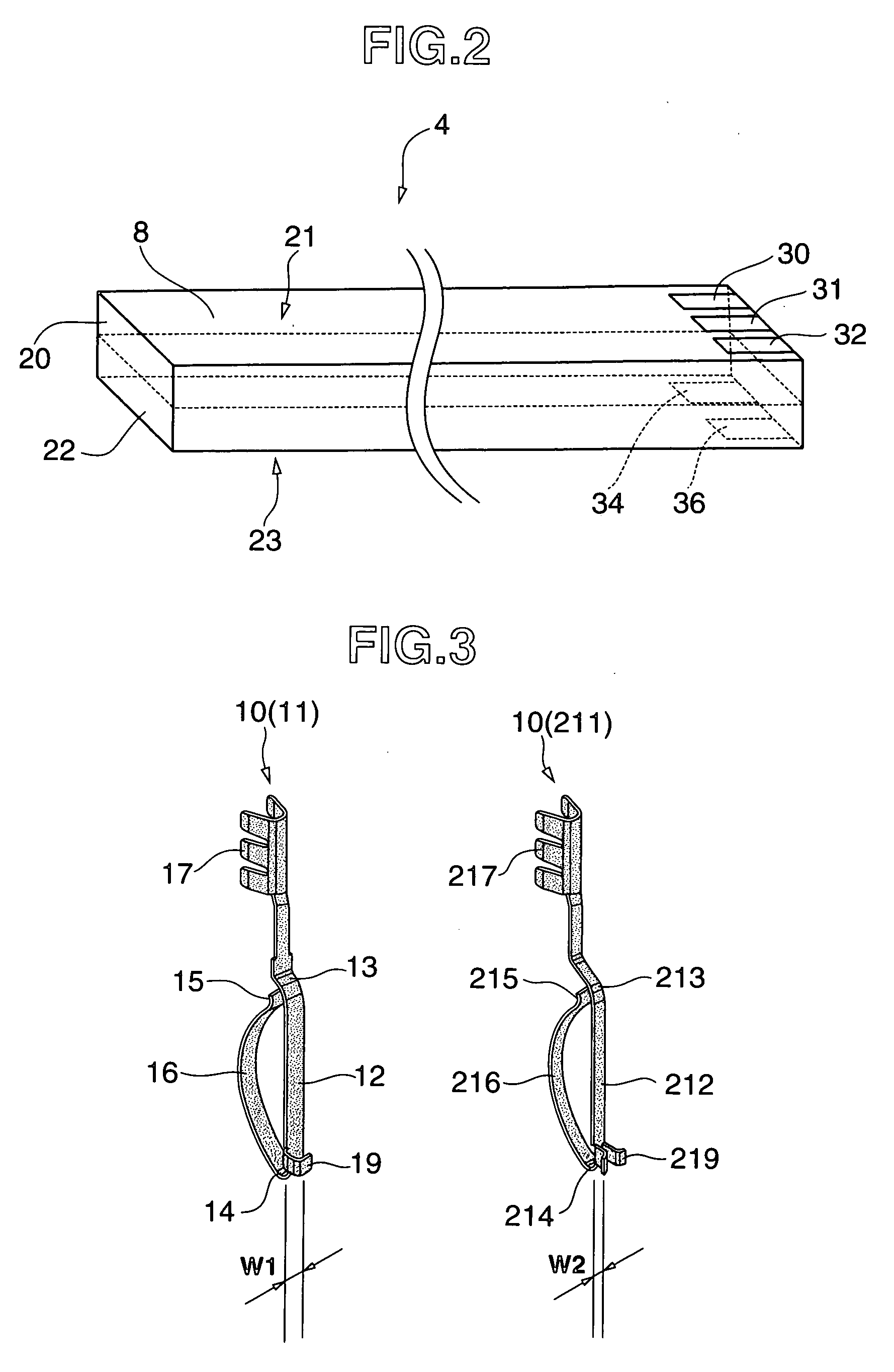
[0045] The air / fuel ratio sensor 2 includes a detection element 4 in the form of a plate extending in an axial direction (up and down direction in the drawing), a tubular metallic housing 102 accommodating the detection element 4 in a way as to allow a front end portion of the dete...


PUM


Abstract

The present invention provides a sensor and a method of producing the same, which makes an electrical connection condition between an electrode terminal section of a detection element and a metallic terminal member good. The sensor includes a lead frame (metallic terminal member) that changes a support condition of supporting an element abutment section for contact with a detection element on a frame main body section, into a one-point support or a two-point support. At a first-half stage of a work for assembly of the lead frame and the detection element, the element abutment section is put in a one-point support condition relative to the frame main body section and the lead frame produces a relatively smaller resilient force, such that it becomes possible to prevent an excessively large pressure from being applied to the detection element. After the assembly work is completed, the element abutment section is put in a two-point support condition relative to the frame main body section and the lead frame produces a larger resilient force as compared with that in the one-point support condition, such that the electrical connection condition between the lead frame and the detection element can be good.

Description

TECHNICAL FIELD [0001] This invention relates to a sensor having a detection element in the form of an axially extending plate and formed with an electrode terminal section at a rear end side and a metallic terminal member contacting the electrode terminal section thereby being electrically connected thereto to form a current path, and a method of producing such a sensor. BACKGROUND TECHNIQUE [0002] Heretofore, it is known a sensor having attached thereto a detection element (sensor element) in the form of an axially extending plate and formed with a detection section at a front end side to face an object to be measured. Enumerated as such a sensor are a gas sensor such as a λ (lambda) sensor, a wide-range air / fuel ratio sensor, oxygen sensor and NOx sensor, and a temperature sensor for detection of temperature. [0003] The plate-shaped detection element is generally configured so as to have a detection section at an axial (longitudinal) front end side and electrode terminal sections...

Claims


Application Information

Patent Timeline
IPC IPC(8): H01T13/20G01N27/407
CPCG01N27/4062G01N27/407G01N27/4077
Inventor MATSUO, KOUJIISHIKAWA, SATOSHI
Owner NGK SPARK PLUG CO LTD
Features
  • Generate Ideas
  • Intellectual Property
  • Life Sciences
  • Materials
  • Tech Scout
  • Unparalleled Data Quality
  • Higher Quality Content
  • 60% Fewer Hallucinations
Learn More