NMR probe for NMR apparatus

Inactive Publication Date: 2007-05-03
HITACHI LTD
5 Cites 3 Cited by

AI-Extracted Technical Summary

Problems solved by technology

As having been explained so far, in the conventional technologies of the low-temperature probe having high sensitivity, the following problem exists: Namely, when the detection coil is manufactured with a normal conducting material, the limit exists to t...

Method used

[0027] In the low-temperature probe, in order to reduce the thermal noise down to a lowest possible limit, an inclusion 10 is cooled down to 20 K or lower. The basic structure of the low-temperature probe includes an outer container 7 for maintaining inside of the probe under vacuum for implementing the heat insulation, and a heat-insulation support structure for supporting the cooled-down inclusion 10.
[0035] Here, L denotes the inductance of the detection coil 1, and rs denotes summation of resistance of the detection coil 1 and resistances of components such as the wirings. For example, by taking advantage of a small-loss (i.e., small-resistance) coil such as the superconducting coil, it becomes possible to enhance the effective Q value of the circuit as is represented by an Expression (2). [Expression⁢ ⁢2] Q1=L+Lscrs(2)
[0038] Unlike the detection coil 1, the compensation coil 4 is not required to detect the signal emitted from the sample 3. Accordingly, the compensation coil 4 is not restricted by such factors as the shape of the coil, shape of the conductor, material of the conductor, and distance of the coil from the sample. Consequently, if possible, a conductor is selected whose shape is comparatively unlikely to undergo influences from outside of the coil, and which result...

Benefits of technology

[0013] According to the present invention, it becomes possible to implement the probe for the NMR apparatus which allo...

Abstract

A NMR probe which causes only a minimum disturbance to magnetic-field uniformity, and which acquires a high resonant Q value. A detection coil 1 for detecting a nuclear magnetic resonance signal emitted from a sample 3 measured, and a compensation coil 4 composed of a superconducting material for compensating for inductance of the detection coil 1 are electrically connected in series with each other. Moreover, a tuning-dedicated variable capacitor 6 is connected to the detection coil 1 in series therewith, and a matching-dedicated variable capacitor 5 is connected to the compensation coil 4 in series therewith. Furthermore, a coaxial cable 9 is connected to both ends of the matching-dedicated variable capacitor 5. This configuration allows detection of the signal.

Application Domain

Magnetic measurementsElectric/magnetic detection +1

Technology Topic

NMR - Nuclear magnetic resonanceVariable capacitor +5

Image

  • NMR probe for NMR apparatus
  • NMR probe for NMR apparatus
  • NMR probe for NMR apparatus

Examples

  • Experimental program(2)

Example

Embodiment 1
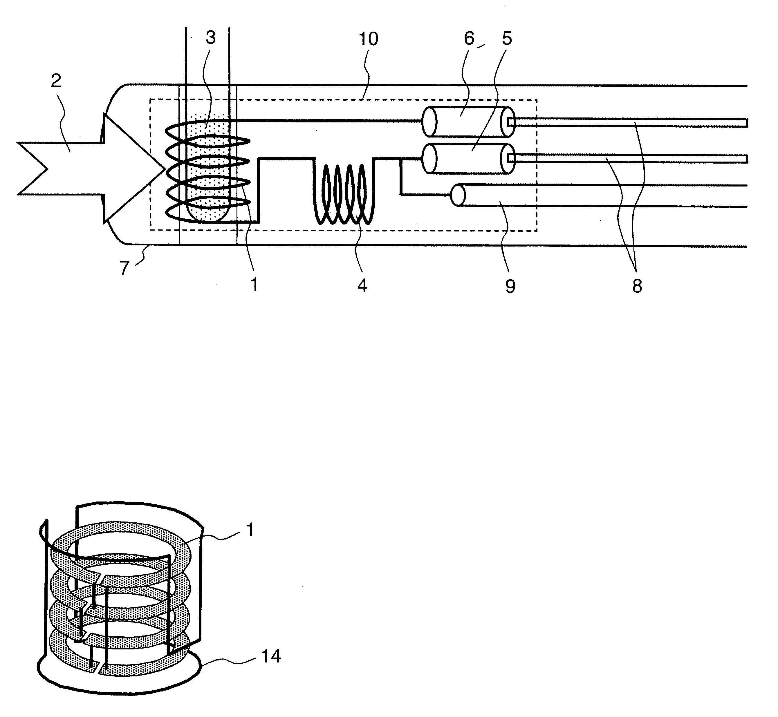
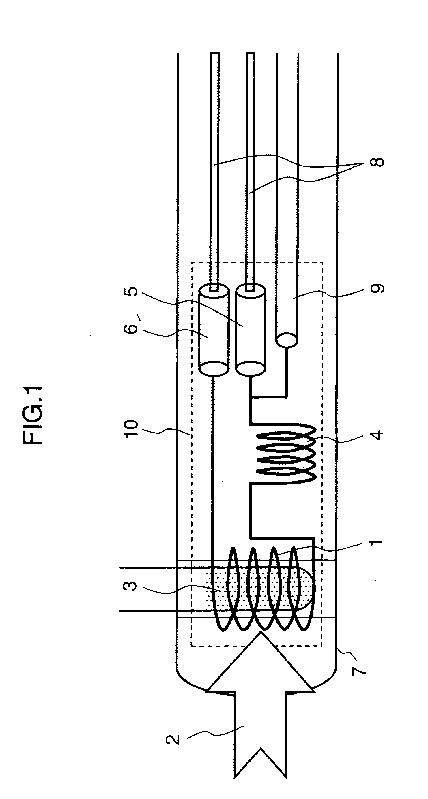
[0026]FIG. 1 illustrates an embodiment of the transmission/reception-separation-type probe circuit according to the present invention. The low-temperature probe in the present embodiment is as follows: A sample 3, i.e., the measurement target, is set up inside the detection coil 1. A uniform static magnetic field 2 is generated in proximity to the detection coil 1 in the direction of the arrow. The direction of the magnetic field to be detected by the detection coil 1 is perpendicular to the direction 2 of the uniform static magnetic field.
[0027] In the low-temperature probe, in order to reduce the thermal noise down to a lowest possible limit, an inclusion 10 is cooled down to 20 K or lower. The basic structure of the low-temperature probe includes an outer container 7 for maintaining inside of the probe under vacuum for implementing the heat insulation, and a heat-insulation support structure for supporting the cooled-down inclusion 10.
[0028] The inclusion 10, which is an area cooled down to the extremely low temperature, includes the detection coil 1, a transmission coil (not illustrated), a reception-dedicated probe circuit (including 4, 5, and 6), and a transmission-dedicated probe circuit (not illustrated). The inclusion 10 also includes a coaxial cable 9 for transferring a radio-frequency wave signal, adjustment shafts 8 for mechanically adjusting the variable capacitors 5 and 6, i.e., the components of the reception-dedicated probe circuit, from the outside, and a RF shield (not illustrated) for shielding the detection coil 1 and the probe circuits from external electrical disturbances. Moreover, the inclusion 10 includes cooling components, such as a pipe (not illustrated) for transporting helium which becomes the refrigerant, and a heat exchanger (not illustrated) cooled down by the helium.
[0029] The reception-dedicated probe circuit includes the compensation coil 4 composed of a superconducting material, the tuning-dedicated variable capacitor 6 and the matching-dedicated variable capacitor 5. In addition, a cooled preamplifier (not illustrated) is set up which is used for amplifying the detected infinitesimal signal with a low noise. For problems such as space, the cooled preamplifier is set up at a portion positioned on the outer side of the magnet inside the probe 15.
[0030] Next, the explanation will be given below concerning electrical characteristics of the NMR probe and the probe circuits of the above-described configuration. The resonant frequency is determined by inductances of the coils and capacitances of the capacitors. Influences of parasitic impedances, such as inductances of wirings, capacitance between the wirings, capacitance between turns of the coils, are suppressed down within the adjustment range of the variable capacitors. Otherwise, the circuit constant is adjusted at the implementation stage.
[0031]FIG. 2 illustrates an equivalent circuit to the probe circuit illustrated in FIG. 1. The influences of the parasitic impedances are suppressed down as described above. As a result, it becomes possible to discuss behavior of the probe circuit in proximity to the resonant frequency by using the equivalent circuit simplified in this way.
[0032] The equivalent circuit illustrated in FIG. 2 is configured by a series connection of the normal conducting detection coil 1, the superconducting compensation coil 4, the tuning-dedicated variable capacitor 6, and the matching-dedicated variable capacitor 5. The coaxial cable 9 is connected to both ends of the matching-dedicated variable capacitor 5 (as illustrated in FIG. 1), thereby detecting the signal. In the adjustment of the equivalent circuit, the component which makes a main contribution to adjustment of the resonant frequency is the tuning-dedicated variable capacitor 6, and the component which makes a main contribution to the impedance matching is the matching-dedicated variable capacitor 5.
[0033] The feature in the present embodiment lies in a point that the embodiment includes the compensation coil 4 which is electrically connected to the detection coil 1 in series therewith. The inductance of the compensation coil 4 is much larger than the inductance of the detection coil 1. The role of the compensation coil 4 lies in a point that the coil 4 explicitly compensates for the inductance of the detection coil 1, and increases the energy to be accumulated in the resonance circuit.
[0034] The Q value before the compensation coil 4 is inserted can be written as is represented by an Expression (1). [ Expression ⁢ ⁢ 1 ] Q 0 = L r s ( 1 )
[0035] Here, L denotes the inductance of the detection coil 1, and rs denotes summation of resistance of the detection coil 1 and resistances of components such as the wirings. For example, by taking advantage of a small-loss (i.e., small-resistance) coil such as the superconducting coil, it becomes possible to enhance the effective Q value of the circuit as is represented by an Expression (2). [ Expression ⁢ ⁢ 2 ] Q 1 = L + L sc r s ( 2 )
[0036] Here, Lsc denotes the inductance of the superconducting compensation coil. Otherwise, if the resistance is comparatively large like the normal conducting coil, the effective Q value is given by an Expression (3). [ Expression ⁢ ⁢ 3 ] Q 2 = L + L nc r s + r nc ( 3 )
[0037] Here, Lnc denotes inductance of the normal conducting compensation coil, and rnc denotes resistance of the normal conducting compensation coil. Accordingly, if the Q value (=Lnc/rnc) of the compensation coil is higher than the Q value (=L/rs) of the detection coil, Q2Q0 holds, and thus the Q value of the circuit can be enhanced. Namely, it becomes possible to enhance the detection sensitivity of the probe. As is shown from the Expression (3), if the inductance Lnc of the compensation coil is larger, the even larger effect can be acquired.
[0038] Unlike the detection coil 1, the compensation coil 4 is not required to detect the signal emitted from the sample 3. Accordingly, the compensation coil 4 is not restricted by such factors as the shape of the coil, shape of the conductor, material of the conductor, and distance of the coil from the sample. Consequently, if possible, a conductor is selected whose shape is comparatively unlikely to undergo influences from outside of the coil, and which results in smallness of the resistance (i.e., loss) of the coil. Also, it is desirable that the size of the entire detention circuit be smaller than a wavelength corresponding to the signal frequency dealt with. For example, as the shape of the coil, there exist toroidal shape and miannda shape. Also, as the material of the conductor, there exist the superconducting materials, the representatives of which are Y-based or Bi-based oxide superconductors, metal-based superconductors such as MgB2 and NbTi, and compound-based superconductors such as Nb3Sn. Otherwise, pure metals such as Cu, Al, Au, and Ag, or composite materials obtained by plating or pasting together these pure metals are conceivable as the material of the conductor. The compensation coil 4 is set at a position about 50 mm away from the sample space. This allows accomplishment of the compatibility between the electrical characteristics and the magnetic characteristics in the entire detention circuit including the detection coil 1.
[0039] As having been explained so far, the compensation coil 4 is connected to the detection coil 1 in series therewith. This makes it possible to enhance the Q value of the probe circuit. As a consequence, there exists an effect of enhancing the sensitivity of the NMR signal detected by the probe.

Example

Embodiment 2
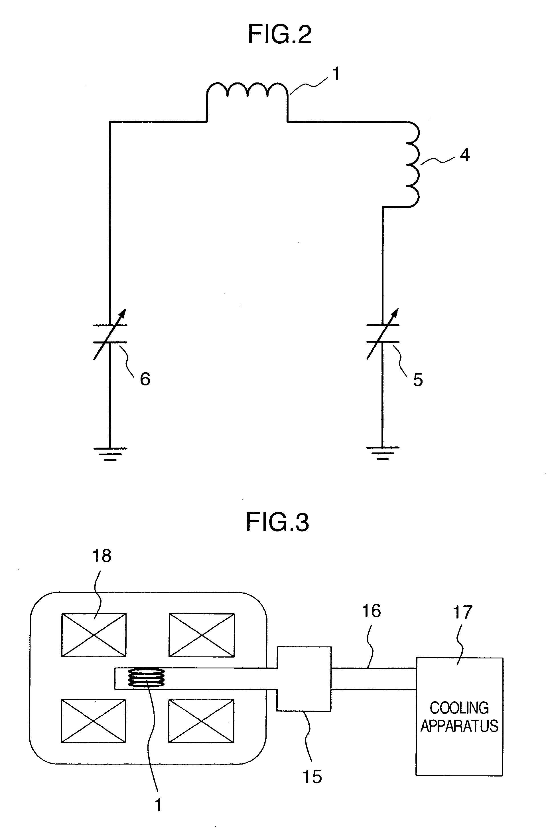
[0040]FIG. 5 illustrates an equivalent circuit to the probe circuit according to a second embodiment of the present invention. In the equivalent circuit illustrated in FIG. 5, another different detection circuit which resonates with a second frequency is connected to the detection circuit of the detection coil (detection coil) 1 illustrated in FIG. 2. The first frequency is the frequency of the nuclear species detected with the high sensitivity in the NMR measurement.
[0041] In FIG. 5, band pass filters (i.e., series resonance filters associated with the second frequency) 13 for implementing isolation between the first frequency and the second frequency are connected to both ends of the detection circuit which is illustrated in the equivalent circuit in FIG. 2 and which resonates with the first frequency. Moreover, a tuning-dedicated variable capacitor 11 associated with the second frequency and a matching-dedicated variable capacitor 12 associated with the second frequency are added to the band pass filters. This circuit configuration forms the equivalent circuit into a duplex tuning circuit where the detection coil 1 resonates with the first frequency and the second frequency.
[0042] If a superconducting material is used as the detection coil 1 in order to enhance the resonant Q value, it becomes substantially rather difficult to co-use the detection coil 1 as a transmission coil which deals with large electric power. This is because of the problem of current capacity which is determined by the critical current characteristic of the superconductivity.
[0043] However, in the circuit of the present embodiment which includes the compensation coil 4, the superconducting material need not be used as the detection coil 1 although the resonant Q value is high. Accordingly, it becomes possible to co-use the detection coil 1 as the transmission coil. If, however, the superconducting material is used as the compensation coil 4 in order to acquire the higher sensitivity, it is difficult to co-use the detection coil 1 with the use of only the first frequency.
[0044] In the resonant loop formed by the tuning circuit associated with the second frequency, the path including the compensation coil 4 comes to exhibit a high impedance, and thus the current scarcely flows therein. This means that the resonant loop is negligible. Consequently, when the superconducting material is used as the compensation coil 4 as well, it becomes possible to perform the transmission/reception at the different frequency without taking into consideration the problem of current capacity of the superconducting coil.
[0045] In the NMR measurement, it has become absolutely necessary to use a lock system for tracking a change in the central magnetic-field intensity due to magnetic-field drift or external disturbances, and controlling the nuclear magnetic resonance frequency. The lock system is also activated by observing the nuclear magnetic resonance signal of a specific atom. It is more advantageous that the nuclear species to be observed by the lock system differ from the nuclear species which is going to be mainly observed in the NMR measurement. For this purpose, deuterium (2H nucleus), i.e., an isotope of hydrogen, is commonly used. This situation requires that the transmission/reception of 1H nucleus and the transmission/reception of 2H nucleus be performed even in a minimum-essential configuration which the probe should implement. Consequently, it is preferable that the other frequency acquired by the method in the present embodiment be allocated to the lock channel.
[0046] As having been explained so far, in the practical detection-circuit configuration which performs the multiplex tuning, it also becomes possible to perform the high-sensitivity measurement by locating the compensation coil which is manufactured using such materials as a superconducting material.
[0047] It should be further understood by those skilled in the art that although the foregoing description has been made on embodiments of the invention, the invention is not limited thereto and various changes and modifications may be made without departing from the spirit of the invention and the scope of the appended claims.

PUM

no PUM

Description & Claims & Application Information

We can also present the details of the Description, Claims and Application information to help users get a comprehensive understanding of the technical details of the patent, such as background art, summary of invention, brief description of drawings, description of embodiments, and other original content. On the other hand, users can also determine the specific scope of protection of the technology through the list of claims; as well as understand the changes in the life cycle of the technology with the presentation of the patent timeline. Login to view more.
Why Eureka
Try Eureka