[0004] Accordingly, it is an
advantage of the present invention to improve upon the current electronic lock box state of the art by eliminating the insecurity of PIN code protection and, instead, enhancing security through the use of biometric identification. The biometric identification data can be coupled with existing electronic keys,
smart card technology, or
wireless technology to facilitate the comparison and
authorization of lock system functions.
[0005] Additional advantages and other novel features of the invention will be set forth in part in the description that follows and in part will become apparent to those skilled in the art upon examination of the following or may be learned with the practice of the invention.
[0006] To achieve the foregoing and other advantages, and in accordance with one aspect of the present invention, a method for operating an electronic lock box system is provided, in which the method comprises the following steps: providing an electronic lock box with a secure compartment therein, a
shackle for attachment to a fixed object, a
processing circuit, and a memory circuit; providing a biometric
identification device that determines observed biometric identification data of a user; storing enrollment biometric identification data in the electronic lock box memory circuit identifying at least one authorized user of the electronic lock box; collecting the observed biometric identification data from a user of the electronic lock box, before at least one operation of the electronic lock box; and preventing operation of the electronic lock box if the observed biometric identification data does not sufficiently correlate to the enrollment biometric identification data stored for an authorized user of the electronic lock box.
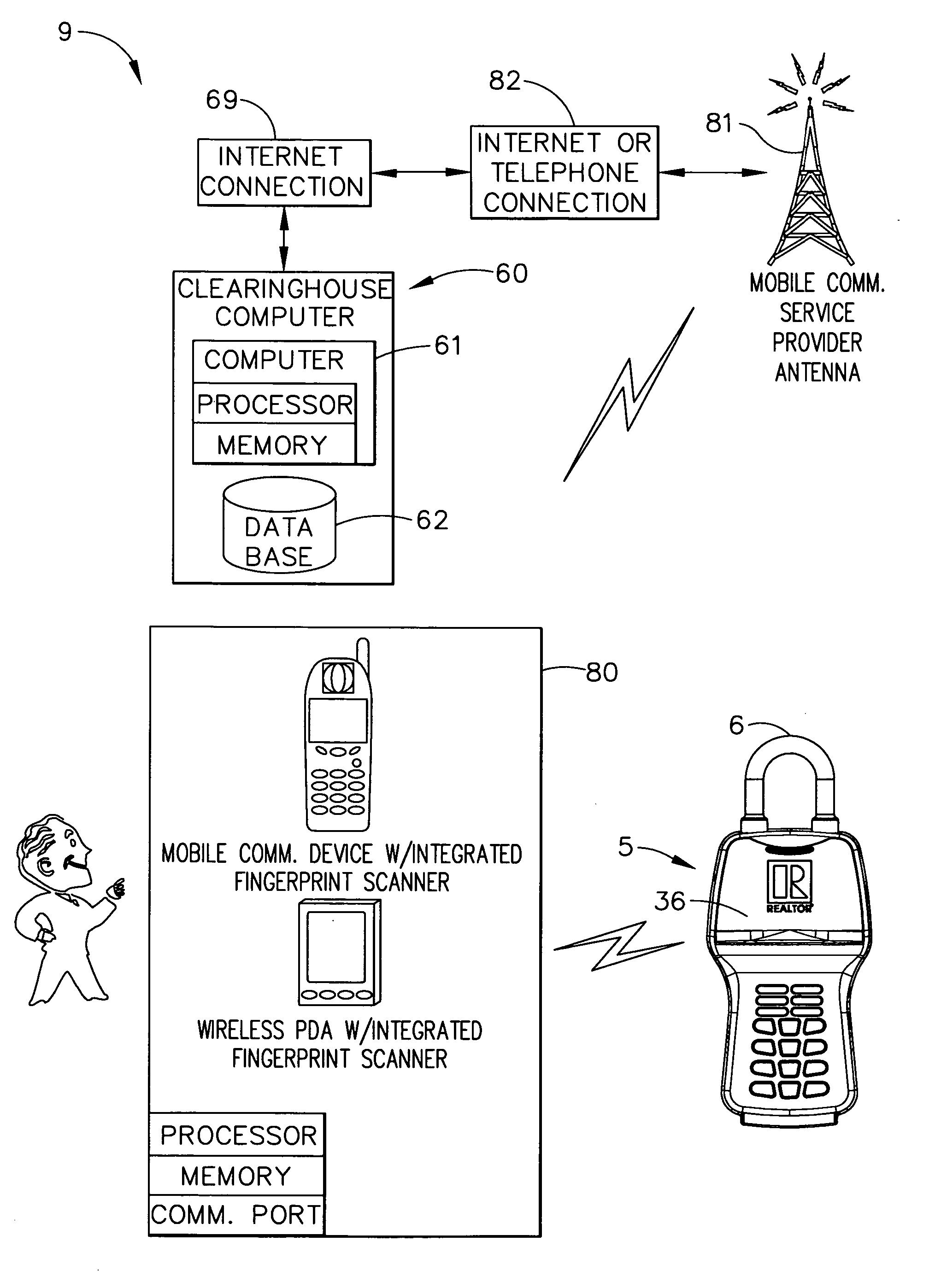
[0007] In accordance with another aspect of the present invention, a method for operating an electronic lock box system is provided, in which the method comprises the following steps: providing an electronic lock box with a secure compartment therein, a
shackle for attachment to a fixed object, a first communications port, and a first
processing circuit; providing an external
portable computer having a second communications port, a second
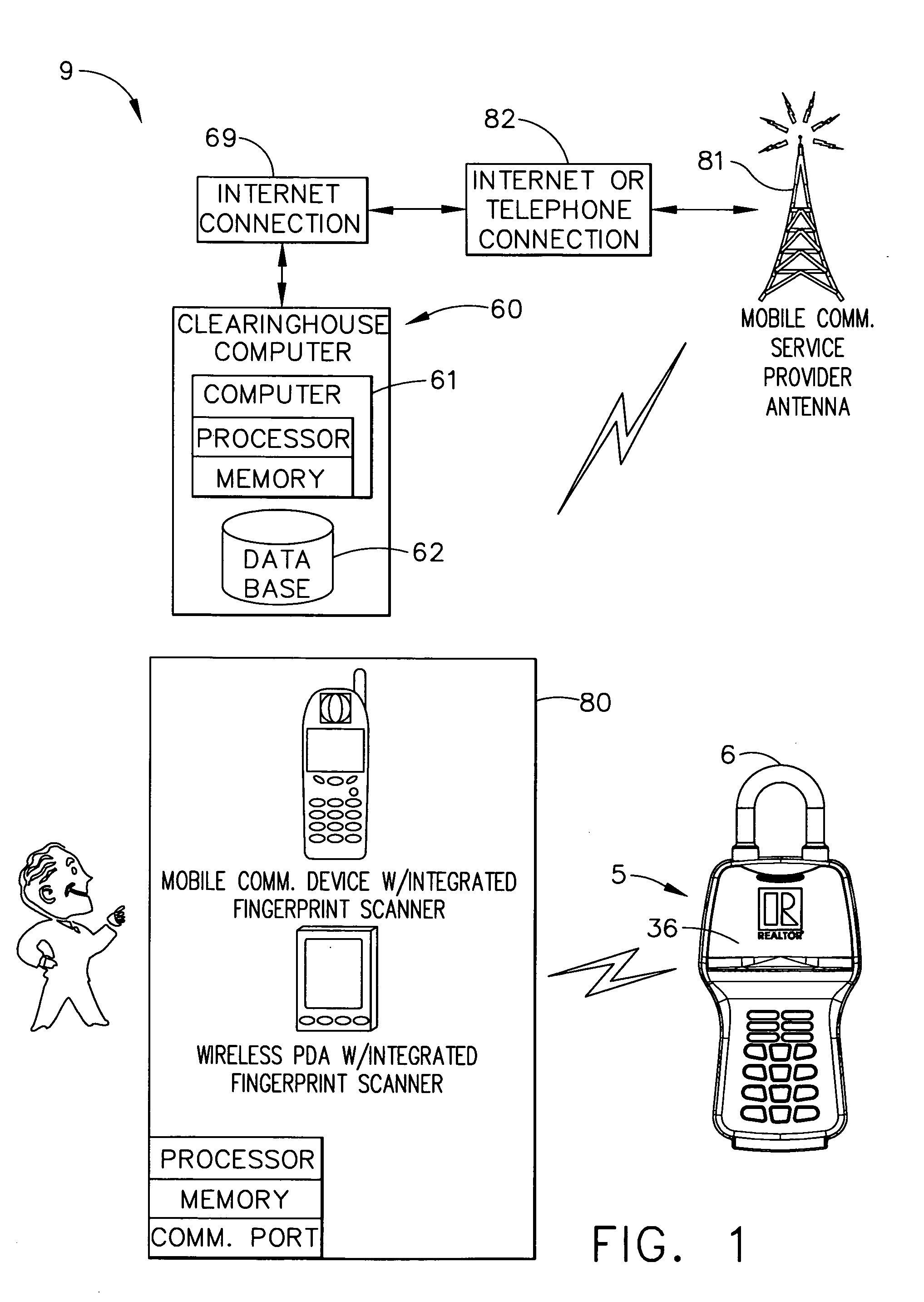
processing circuit, and a memory circuit; providing a biometric
identification device that determines observed biometric identification data of a user; storing enrollment biometric identification data in the external
portable computer memory circuit identifying at least one authorized user of the electronic lock box; collecting the observed biometric identification data from a user of the electronic lock box, before at least one operation of the electronic lock box; and preventing operation of the electronic lock box if the observed biometric identification data does not sufficiently correlate to the enrollment biometric identification data stored for an authorized user of the electronic lock box.
[0008] In accordance with yet another aspect of the present invention, a method for operating an electronic lock box system is provided, in which the method comprises the following steps: providing an electronic lock box with a secure compartment therein, a
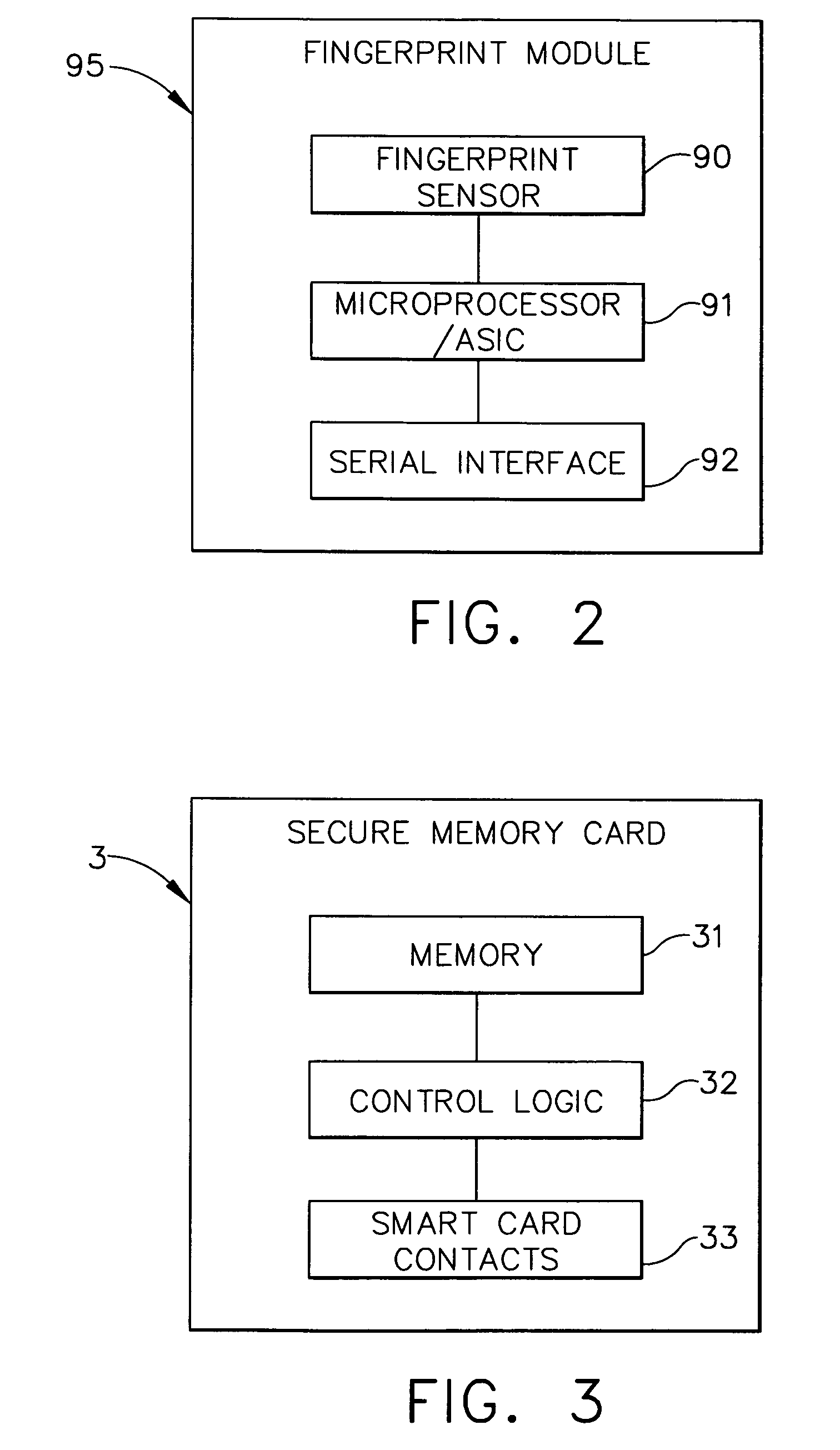
shackle for attachment to a fixed object, and a processing circuit; providing a portable memory device; providing a biometric
identification device that determines first biometric identification data of a user; providing a
display device for displaying electronic lock box
system information; and conditionally displaying a secure compartment access code on the
display device if a sufficient correlation occurs between the first biometric identification data, and second biometric identification data that has been stored in the portable memory device.
[0009] In accordance with still another aspect of the present invention, a method for operating an electronic lock box system is provided, in which the method comprises the following steps: providing an electronic lock box with a secure compartment therein, a shackle for attachment to a fixed object, and a processing circuit; providing a portable memory device, which interfaces to the electronic lock box processing circuit; providing a biometric identification device that determines first biometric identification data of a user; providing a communications link used for exchanging data between (a) the biometric identification device, and (b) one of: (i) the electronic lock box processing circuit, and (ii) the portable memory device; and authorizing secure compartment access if a sufficient correlation occurs between the first biometric identification data, and second biometric identification data that has been stored in the portable memory device.

