Unlock instant, AI-driven research and patent intelligence for your innovation.

Multi-depth displays

Inactive Publication Date: 2007-05-03
SHARP KK
View PDF11 Cites 50 Cited by
  • Summary
  • Abstract
  • Description
  • Claims
  • Application Information

AI Technical Summary

Benefits of technology

[0017] A multi-depth display apparatus of the present invention for displaying images at at least two different perceived depths comprises a display panel comprising a plurality of pixels arranged to display at least a first image and a second image; and a direction changing layer arranged so that light forming said first and second images enters the direction changing layer and then exits the direction changing layer, wherein: in relation to the light forming said first image, the direction of the light is changed by the direction changing layer so that the light exiting

Problems solved by technology

One factor that has limited the widespread acceptance of such displays is the realism with which they can represent the instruments.
The prior art teaches us how to make stereoscopic and auto-stereoscopic displays from a single panel, however, these devices produce a stereo image pair rather than true depth.
Drawbacks of auto-stereoscopic displays include: limited head freedom, and eye strain due to conflicting depth cues (convergence—accommodation).
This generates the multiple depth effect but requires large, expensive film apparatus and a bulky series of mirrors 10, 12, 14 to create the path difference.
The display uses multiple SLMs which makes the system expensive compared to a standard display.
Drawbacks are the same as above for multiple panel displays, but in addition they can only show limited images as dictated by electrode patterns.
In this case the light is transmitted to the environment which would not be suitable for an automotive display, particularly for night time driving.
In addition multiple displays make the system expensive.
These types of display also have slow switching times and are not suitable for the wide temperature ranges of the automotive environment.
Time sequential projection requires the device to operate faster than video rate, which is difficult with current technologies over a wide temperature range.
Also, synchronisation with shutters is required, and the system is bulky due to projection optics.
However, this requires extra volume as two displays must be at an angle to each other, and the multiple displays make the system expensive.
This embodiment is bulky and costly due to using two displays.
Two mirror elements 40, 42 are required per section which is both bulky and costly.
Any aberration in the lenses would cause image distortion as the viewer moves relative to the display even if it is perfectly compensated on axis.

Method used


Image

  • Multi-depth displays
  • Multi-depth displays
  • Multi-depth displays

Examples


Embodiment Construction

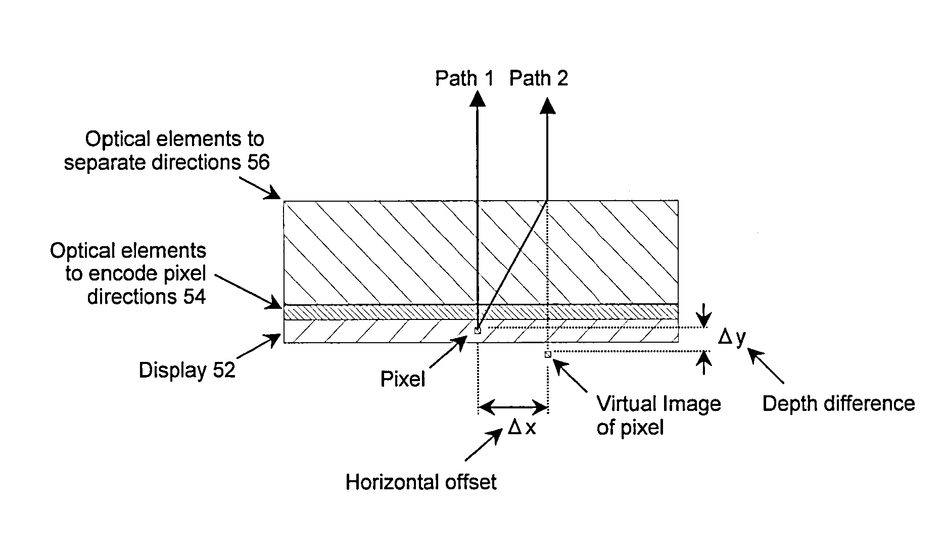
[0041]FIG. 7 shows the general concept of a single display 52 that can produce multiple images multiplexed in either angle, polarisation, time or wavelength followed by optics 54, 56 which cause the multiplexed images to take different optical paths to the user, such that they are observed to overlap at different depths. There are a number of ways the optical paths can be altered depending on the method of multiplexing; for example using a birefringent material, or by diffractive, refractive or mirrored elements.

[0042] Multiplexed images are then shown on the display corresponding to the multiple planes of the required output. FIG. 8 shows an example pair of images 58, 60 for an automotive application and the corresponding interlaced image 62 that could be shown on a spatially multiplexed display.

[0043] A first embodiment is shown in FIG. 9. It consists of a multi-view display 64; that is, a display that can produce independent images multiplexed in angle. This could be, for examp...


PUM


Abstract

A multi-depth display apparatus comprises: a display panel comprising pixels arranged to display first image and second images; and a direction changing layer arranged so that light forming said first and second images enters the layer and then exits the layer, wherein: in relation to the light forming said first image, the direction of the light is changed by the layer so that the light exiting the layer is changed in direction by a first angle relative to the light entering the layer; in relation to the light forming said second image, the direction of the light is changed by the layer so that the light exiting the layer is changed in direction by a second angle relative to the light entering the layer; and said first and second angles are different to create a difference in perceived depth between said first and second images when viewed by a user.

Description

[0001] This Nonprovisional application claims priority under 35 U.S.C. § 119(a) on UK Patent Application No. 0522142.9 filed in the United Kingdom on Oct. 31, 2005, the entire contents of which are hereby incorporated by reference. FIELD OF THE INVENTION [0002] The invention relates to multi-depth display devices methods. BACKGROUND OF THE INVENTION [0003] Some vehicles now contain a display in the dashboard to show the instrument cluster rather than more commonplace mechanical dials. One factor that has limited the widespread acceptance of such displays is the realism with which they can represent the instruments. The current invention attempts to address this issue by describing a display that can produce multiple images at different depths using only a single display as an image source. Such a display could show the instrument panel at one depth and the needles and warning indicators floating above it. This would increase both the visibility and realism of the instruments leading...

Claims


Application Information

Patent Timeline
IPC IPC(8): G09G5/00G02B5/30G02B17/00G02B27/00G02B27/01G02B27/22G02B27/42
CPCG02B5/30G02B17/006G02B27/0101G02B27/2278G02B27/42G02B27/4205G02B2027/011G02B2027/0127G02B30/52B60K35/00G02F1/1335G02B30/40
Inventor WYNNE-POWELL, THOMASMONTGOMERY, DAVIDEVANS, ALLAN
Owner SHARP KK
Features
  • R&D
  • Intellectual Property
  • Life Sciences
  • Materials
  • Tech Scout
  • Unparalleled Data Quality
  • Higher Quality Content
  • 60% Fewer Hallucinations
Learn More