Display driving circuit

Inactive Publication Date: 2007-05-03
RENESAS ELECTRONICS CORP
View PDF3 Cites 91 Cited by
  • Summary
  • Abstract
  • Description
  • Claims
  • Application Information

AI Technical Summary

Benefits of technology

[0018] Further, especially, the display panel is a liquid crystal panel, and the display unit is a liquid crystal display. The illumination device is a device that, when for example a single backlight is turned ON, illumin

Problems solved by technology

However, in this second method, since it is necessary to hold all the data of histogram of an image for the control, the scale of the logic circuit for the hist

Method used


Image

  • Display driving circuit
  • Display driving circuit
  • Display driving circuit

Examples


Example

First Embodiment

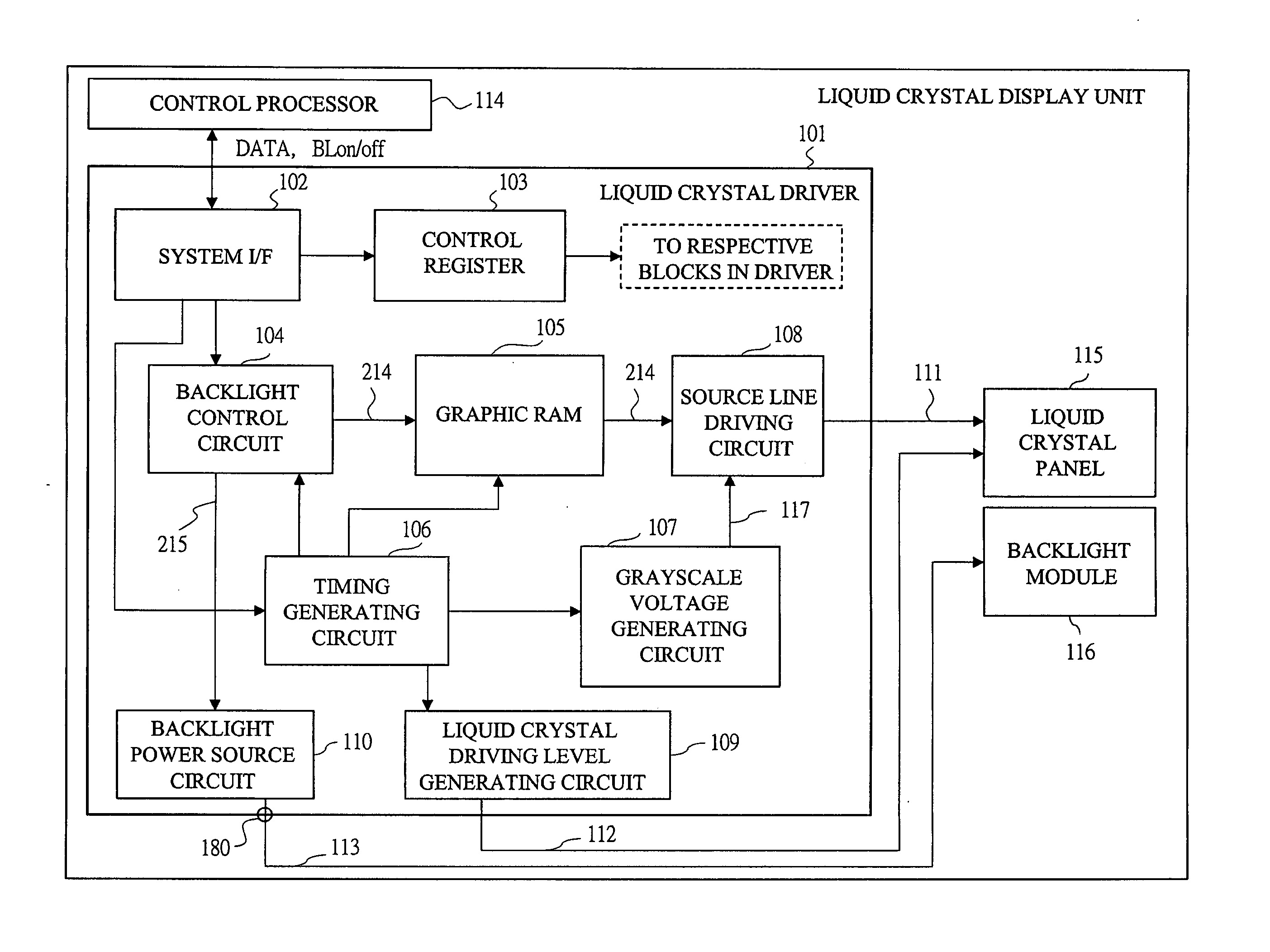
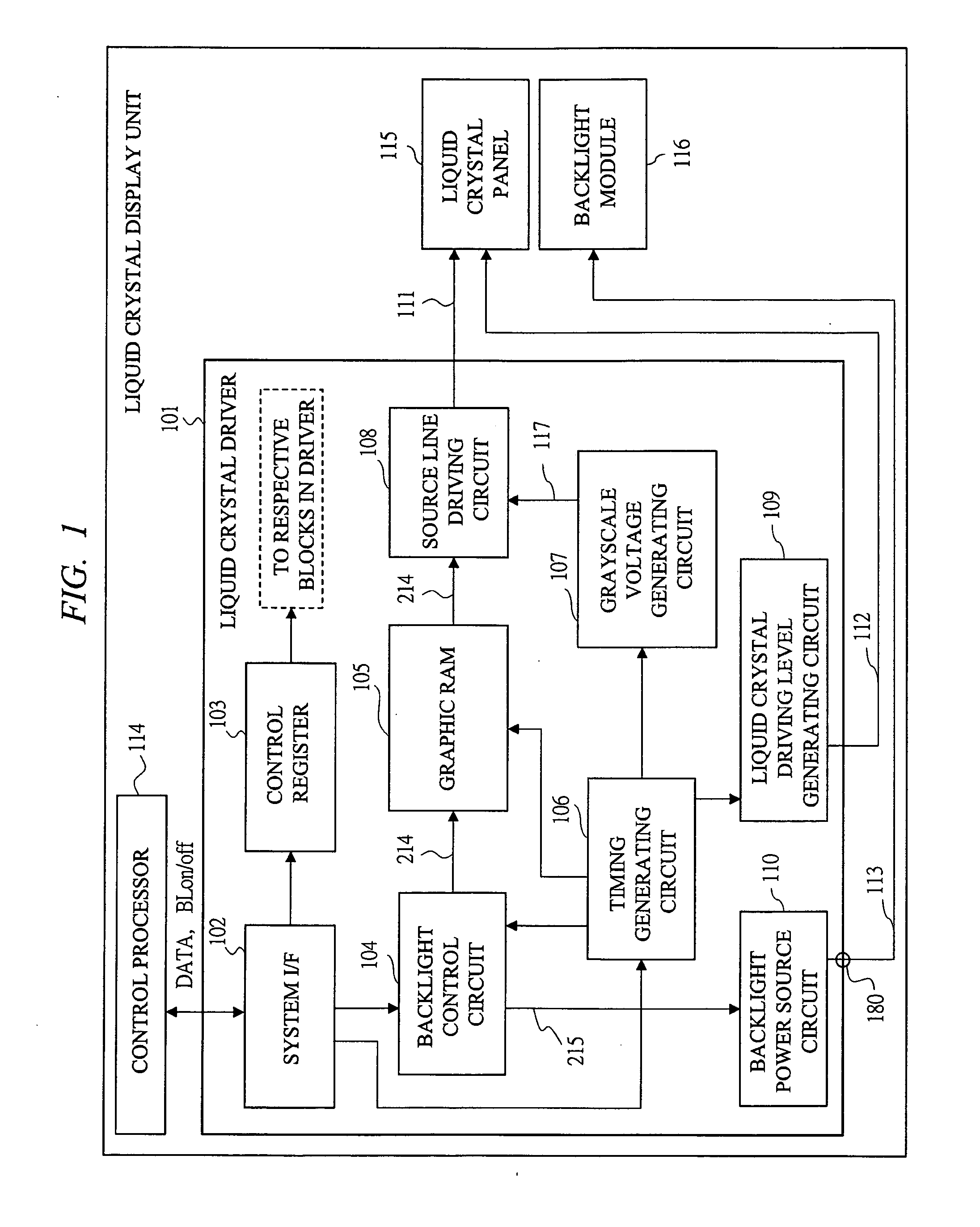
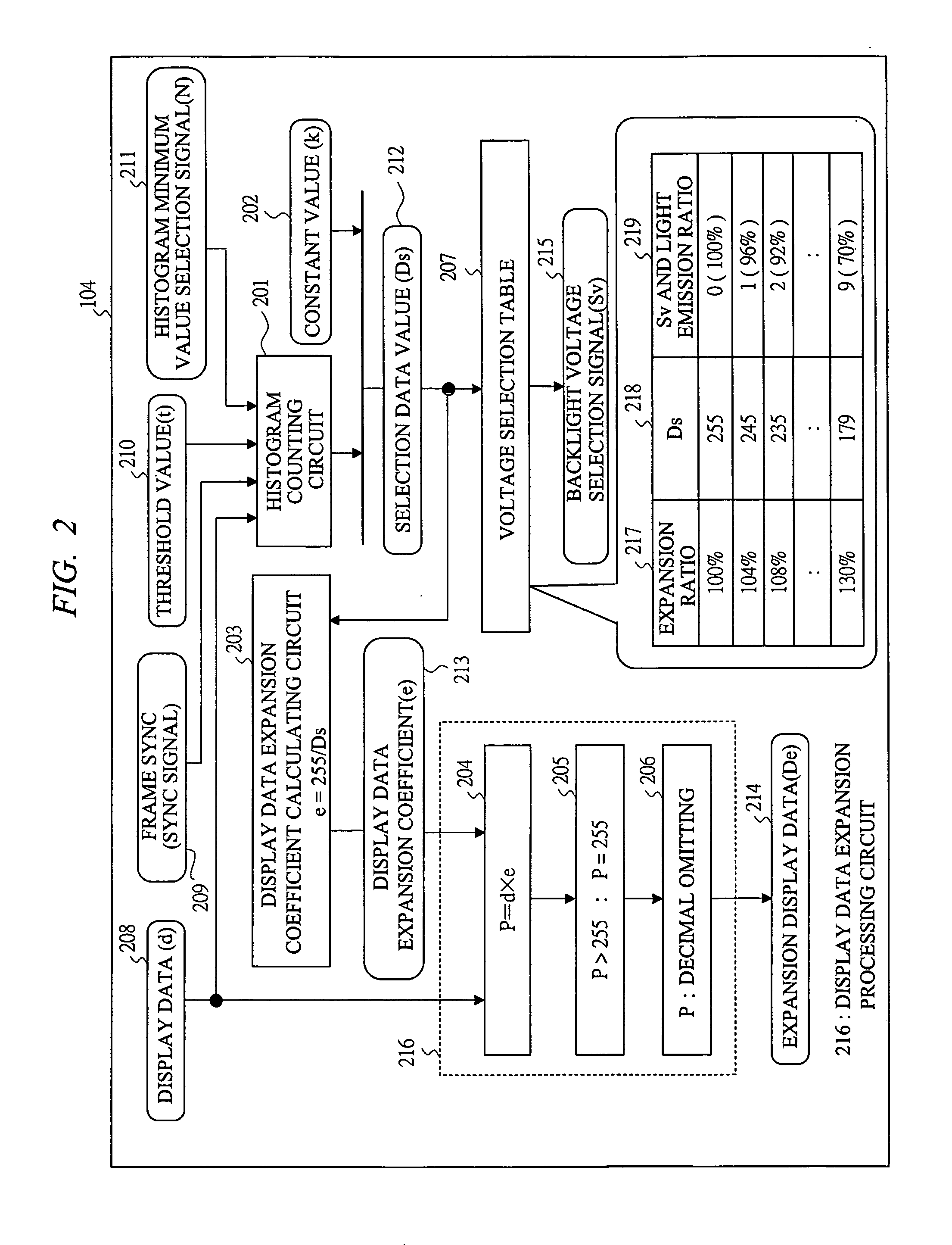
[0048]FIG. 1 shows a structure of a liquid crystal display unit including a liquid crystal driver 101 and the peripheral thereof according to a first embodiment. FIG. 2 shows a structure and processing of a backlight control circuit 104 in the liquid crystal driver 101. FIG. 3 shows a processing by use of a partial histogram as the characteristic control in the liquid crystal driver 101. FIG. 4 shows a control processing flowchart in the liquid crystal driver 101. FIG. 6 shows a schematic structure of illumination and display by a backlight in the present liquid crystal display unit.

[0049] In FIG. 1, the present liquid crystal display unit has a structure including a control processor 114, a liquid crystal driver 101, a liquid crystal panel 115, and a backlight module 116. The control processor 114 controls the entire liquid crystal display unit including the liquid crystal driver 101. The present liquid crystal display unit is a liquid crystal display or the like ...

Example

Second Embodiment

[0085] Next, a second embodiment is explained hereinafter. FIG. 5 shows a structure of a liquid crystal display unit including a liquid crystal driver 101B and the vicinity thereof according to the second embodiment. In comparison with the first embodiment, the backlight power source circuit 110 is not arranged inside of the liquid crystal driver 101B, instead, a backlight external power source circuit 501 having the function equivalent to that of the backlight power source circuit 110 is arrange outside of the liquid crystal driver 101B, and inside of the liquid crystal display unit. It outputs a backlight control signal 502 (corresponding to the backlight voltage selection signal 215) from the liquid crystal driver 101B, and thereby controls the backlight external power source circuit 501 in the same manner as in the first embodiment. The control itself of the backlight power saving function is same as that in the first embodiment.

[0086] As the action, by the in...

Example

Third Embodiment

[0088] Next, a third embodiment is explained with reference to FIG. 7 through FIG. 9 hereinafter. In the above first embodiment, the histogram data to be held can be structured not to all the pixel values (0˜255) but to only the values of the significant partial range (for example, 183˜255), and the scale of the necessary logic circuit is reduced accordingly, thereby the backlight emission amount control for practical use is realized. In a liquid crystal driver according to the third embodiment, further, the upper limit of the histogram hold objective is not fixed to 255 (pixel value), but both the upper limit and the lower limit are set, thereby the control is made more flexible. Further more, the embodiment can easily cope with a display having different gamma curves.

[0089]FIG. 7 shows a block structure of a histogram counting circuit 601 (circuit corresponding to the 201) in the third embodiment. The histogram counting circuit 601 has an entry data generating ci...


PUM


Abstract

In a display driving circuit according to the present invention, not all the pixel values (example : 0˜255) but only the values (example : 179˜255) of the significant partial range (N˜100%) have data of histogram of pixels of an image as a partial histogram, and when the pixel (Ds) at the significant t% rank order of the entire histogram is within the range of the partial histogram, the display driving circuit performs its operation in the same manner as in the case where it has the entire histogram, and when the pixel (Ds) is out of the range, the display driving circuit uses the range minimum value (N) in the place of the pixel of the significant t% rank order and performs its operation.

Description

CROSS-REFERENCE TO RELATED APPLICATION [0001] The present application claims priority from Japanese Patent Application No. JP 2005-298891 filed on Oct. 13, 2005, Japanese Patent Application No. JP 2006-011144 filed on Jan. 19, 2006, and Japanese Patent Application No. JP 2006-228563 filed on Aug. 25, 2006, the contents of which are hereby incorporated by reference into this application. TECHNICAL FIELD OF THE INVENTION [0002] The present invention relates to a display unit such as a liquid crystal display and the like and an art of a driving circuit thereof, more specifically, it relates to an art of the control of illumination and display in a display unit equipped with illumination means such as a backlight and the like. BACKGROUND OF THE INVENTION [0003] In recent years, liquid crystal displays are loaded in battery driven information devices, for example cell phones and the like. Most of these displays are of transmissive types and semi transmission types that require backlights...

Claims


Application Information

Patent Timeline
IPC IPC(8): G09G3/36
CPCG09G3/2092G09G3/3406G09G3/3611G09G2320/0247G09G2320/0271G09G2320/04G09G2320/0633G09G2320/0646G09G2320/0653G09G2320/0673G09G2330/021G09G2360/16G09G2360/18G09G3/36G02F1/133G09G3/20
Inventor KUROKAWA, YOSHIKIKUDO, YASUYUKIKUMAGAI, TOSHIYUKISAKAMAKI, GORO
Owner RENESAS ELECTRONICS CORP
Why Eureka
Try Eureka