Head mounted display with eye accommodation
- Summary
- Abstract
- Description
- Claims
- Application Information
AI Technical Summary
Benefits of technology
Problems solved by technology
Method used
Image

Examples
Embodiment Construction
[0049] Before explaining the disclosed embodiments of the present invention in detail it is to be understood that the invention is not limited in its application to the details of the particular arrangements shown since the invention is capable of other embodiments. Also, the terminology used herein is for the purpose of description and not of limitation.
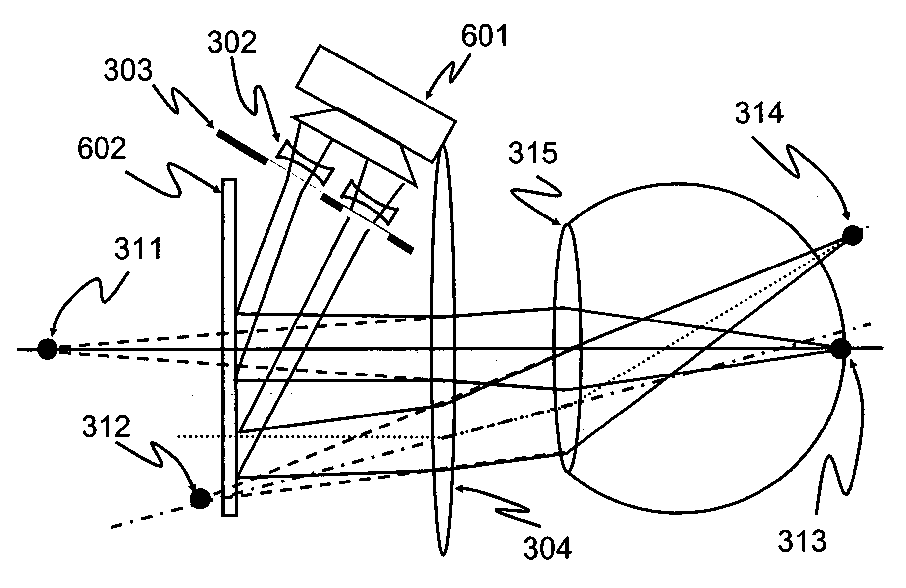
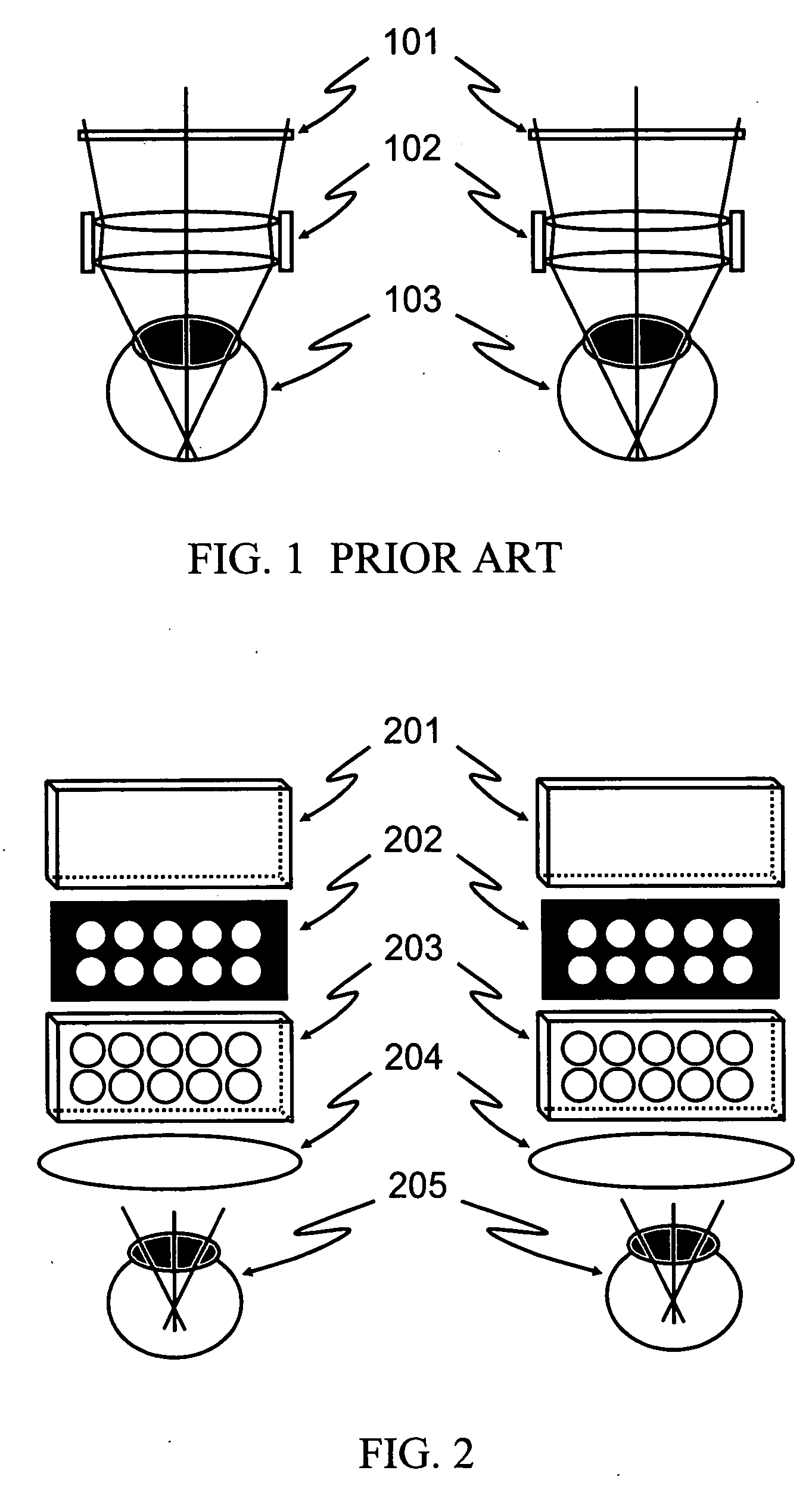
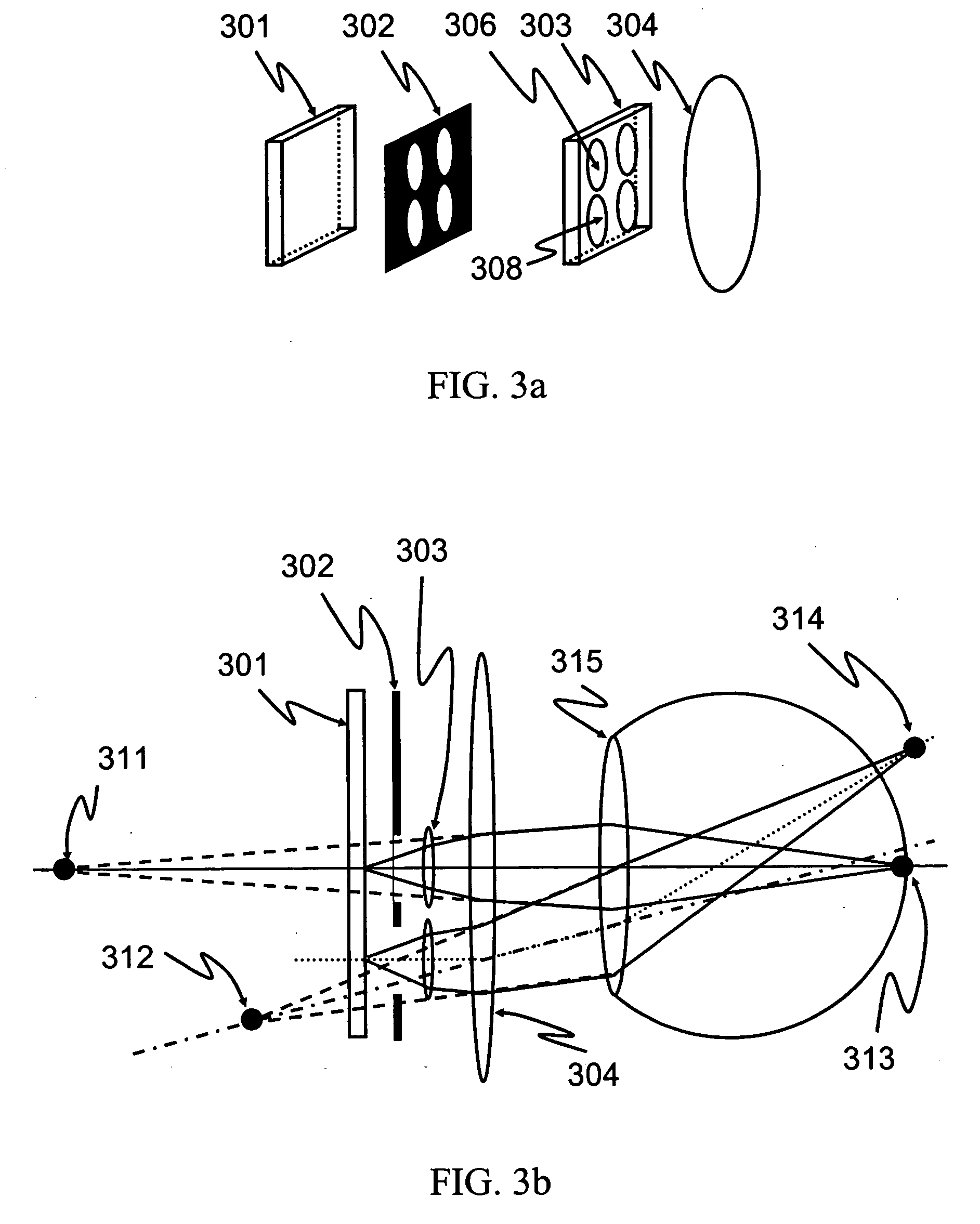
[0050] The following is a list of the designators used in the drawings and the detailed specification to identify components, wherein like components assigned like designators: 1011 display screens 25205 eyes 102 image lenses 206 liquid crystal micro-lens 103 eyes 301 planar emissive LC display screen 201 planar display screens 302 planar black mask 202 planar black masks 303 planar tunable focus LC lens array 203 planar tunable focus LC lens arrays 30304 bias lens 204 planar bias lens 306 liquid crystal micro-lens 308 liquid crystal micro-lens 25812 virtual object of display pixel 2311 virtual object of display pixel 1813 retinal ...
PUM
 Abstract
Description
Claims
Application Information
PatSnap Eureka turns technology decisions into work you can execute. Powered by our Innovation Knowledge Graph, it runs expert workflows across engineering, life sciences, materials and intellectual property. Get your review-ready output in minutes.


