Dual panel display and method for improving display performance thereof
a display panel and display technology, applied in the field of dual panel display, can solve the problems of difficult to achieve satisfying performance, complicated method of designing the pattern of the light guide plate, and high cost, and achieve the effect of improving local optical properties, improving optical properties, and improving the window problem or uneven brightness of the main display panel
- Summary
- Abstract
- Description
- Claims
- Application Information
AI Technical Summary
Benefits of technology
Problems solved by technology
Method used
Image
Examples
first embodiment
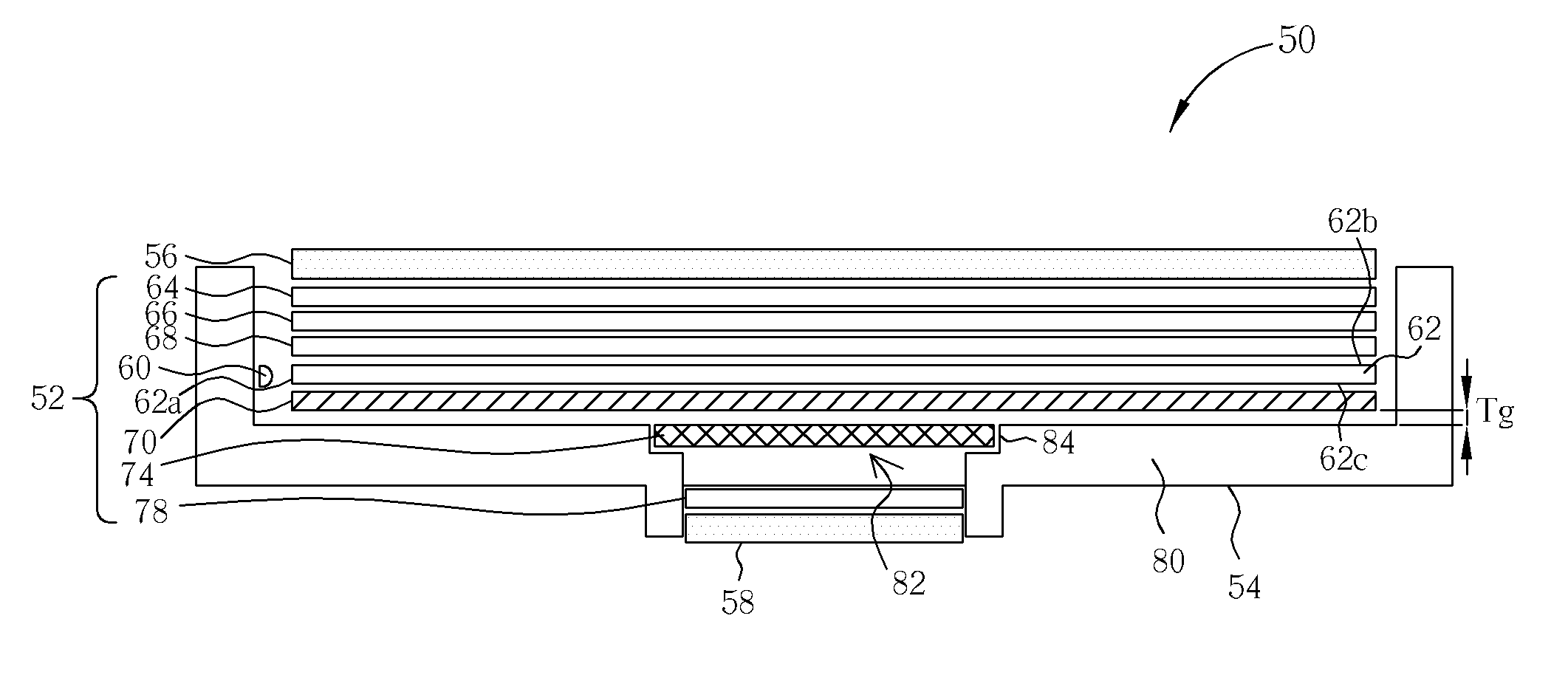
[0026] Referring to FIG. 4, FIG. 4 is a sectional schematic diagram of a dual panel display according to the present invention. As shown in the figure, the present invention dual panel display 50 comprises a backlight module 52, a housing 54, a main display panel 56 and a sub-display panel 58 having a size smaller than the size of the main display panel 56. The housing 54 comprises a fixing plane 80 for positioning the main display panel 56 and the sub-display panel 58. The fixing plane 80 has an opening 82 with a size approximately the same as the size of the sub-display panel 58 so that light produced by the backlight module 52 can pass through the opening 82 to the sub-display panel 58. The backlight module 52 comprises a light guide plate 62, made of a plastic material, having a light-incidence surface 62a, a first light-exit surface 62b, and a second light-exit surface 62c, wherein the first light-exit surface 62b and the second light-exit surface 62c are adjacent to the light-...
second embodiment
[0031] Referring to FIG. 9, FIG. 9 is a dual panel display according to the present invention, wherein the numerals of elements in FIG. 9 is the same as that in FIG. 4 for explanation. The dual panel display 50 in FIG. 9 also comprises a backlight module 52, a main display panel 56, and a sub-display panel 58 fixed on a housing 54. It should be noted that the backlight module 52 of this embodiment comprises two transflective films 70 and 72, and each of the transflective films 70, 72 may be respectively selected form the group consisting of transparent sheet, dual brightness property enhancement film, lens, reflection film, diffuser film, and films that can adjusting its transmission rate or reflection rate, which means the transflective films 70, 72 may be the same material films or different material films. FIG. 10 is a diagram shows that the transflective films 70 and 72 are a lens and a diffuser film respectively. As shown in the figure, the surface of the transflective film 70 ...
third embodiment
[0032] With reference to FIG. 12, FIG. 12 is a sectional schematic diagram of a dual panel display according to the present invention. The dual panel display 100 in FIG. 12 comprises a backlight module 102, a main display panel 106, a sub-display panel 108, and a housing 104 with a fixing plane 124. The backlight module 102 is positioned between the main display panel 106 and the fixing plane 124, and includes a diffuser film 116, a prism film 114, a diffuser film 112, a light source 110, a light guide plate 111, and a transflective film 118 from top to bottom. The size of the sub-display panel 108 is smaller than that of the main display panel 106, and the fixing plane 124 has an opening 126 so that the backlight module 102 can provide light to the sub-display panel 108. In addition, the dual panel display 100 further comprises a diffuser film 122 positioned between the sub-display panel 108 and the housing 104, and an optical property enhancement film 120 positioned between the di...
PUM
| Property | Measurement | Unit |
|---|---|---|
| thickness | aaaaa | aaaaa |
| size | aaaaa | aaaaa |
| optical property | aaaaa | aaaaa |
Abstract
Description
Claims
Application Information
 - R&D
- Intellectual Property
- Life Sciences
- Materials
- Tech Scout
- Unparalleled Data Quality
- Higher Quality Content
- 60% Fewer Hallucinations
Browse by: Latest US Patents, China's latest patents, Technical Efficacy Thesaurus, Application Domain, Technology Topic, Popular Technical Reports.
© 2025 PatSnap. All rights reserved.Legal|Privacy policy|Modern Slavery Act Transparency Statement|Sitemap|About US| Contact US: help@patsnap.com


