Dc motor drive unit

a dc motor and drive unit technology, applied in the direction of dc motor speed/torque control, motor/generator/converter stopper, control system, etc., can solve the problems of increasing the cost of the drive circuit, limiting the controllable speed range of the motor, and the minimum permissible rotational speed of the motor can be reduced, so as to improve the start-up capability of the dc motor and widen the controllable speed range after the startup

Inactive Publication Date: 2007-05-03
ROHM CO LTD
View PDF3 Cites 16 Cited by
  • Summary
  • Abstract
  • Description
  • Claims
  • Application Information

AI Technical Summary

Benefits of technology

[0022] Moreover, since the DC motor is driven by PWM pulses of predetermined duty ratios during the acceleration period and by PWM pulses of a duty ratio based on speed instruction data after the acceleration period, the startup capability of the DC motor is improved and the minimum permissible rotational speed of the motor can be reduced. That is, the motor can be securely started up at all times, and the range of controllable speed of the motor after the startup can be broadened.

Problems solved by technology

Therefore, it is necessary to configure the transistor 2 and the power source to withstand such large startup current level Ip, which raises the cost of the drive circuit.
Since the startup current is reduced in accordance with the duty ratio, a startup failure can take place if the startup current is too small to generate a necessary startup torque.
Therefore, it is not possible to arbitrarily set the minimum rotational frequency of the DC motor 1, so that the range of controllable speed of the motor is limited.
However, the motor consumes wasteful electric power since the motor is provided with current even when it is not in operation.
Moreover, in the method of the Patent Document 1, the range of the rotational speed of the DC motor that can be regulated by adjusting the duty ratio of the PWM pulses is limited like the conventional drive circuit shown in FIG. 5, due to the fact that a bias current, though it is small enough not to rotate the motor, is flowing through the switching transistor.

Method used


Image

  • Dc motor drive unit
  • Dc motor drive unit
  • Dc motor drive unit

Examples


Embodiment Construction

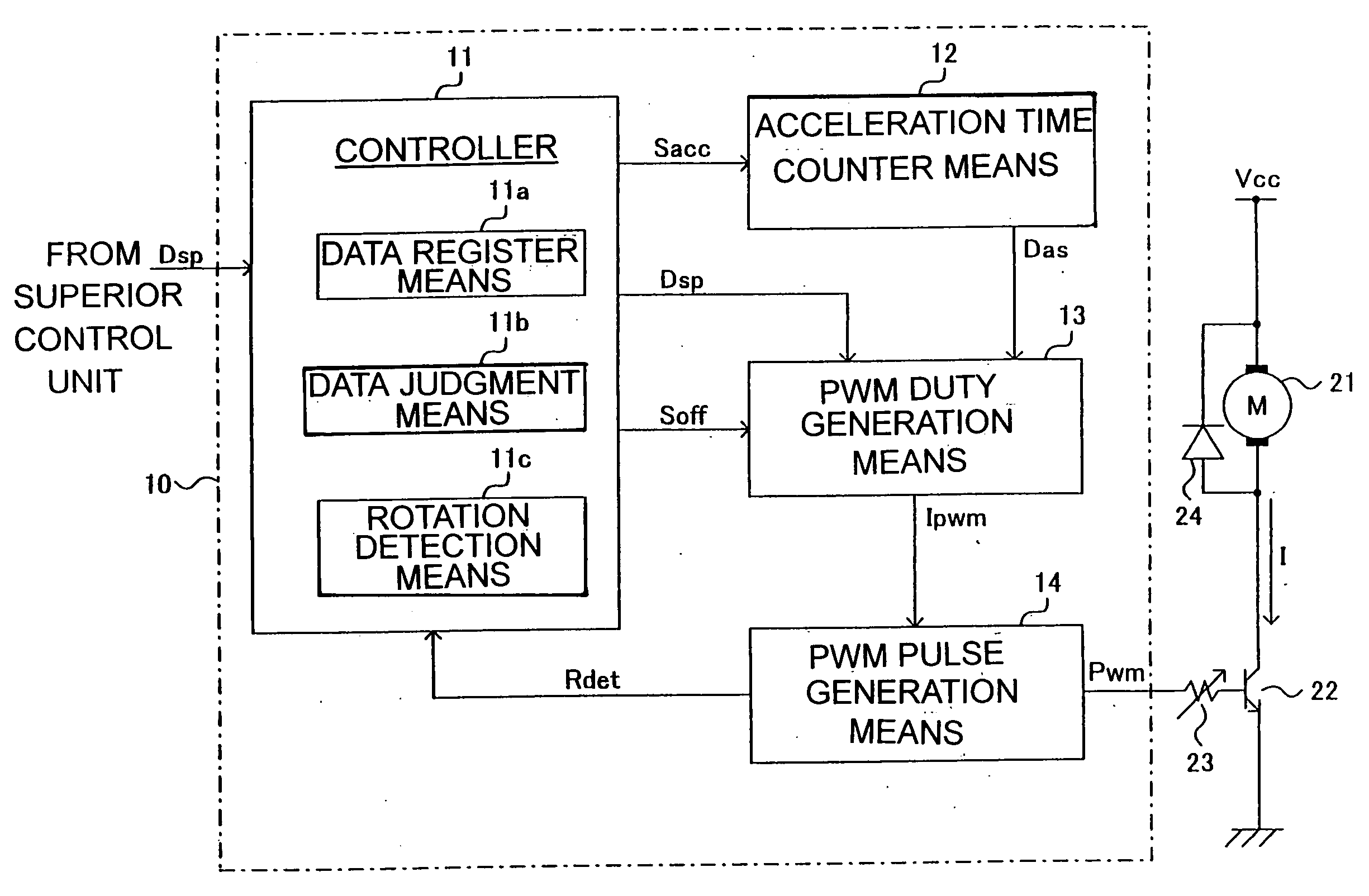
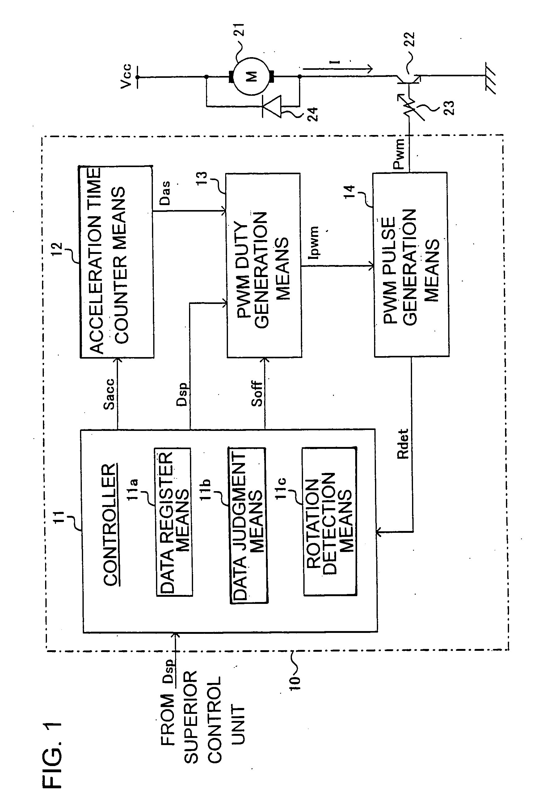
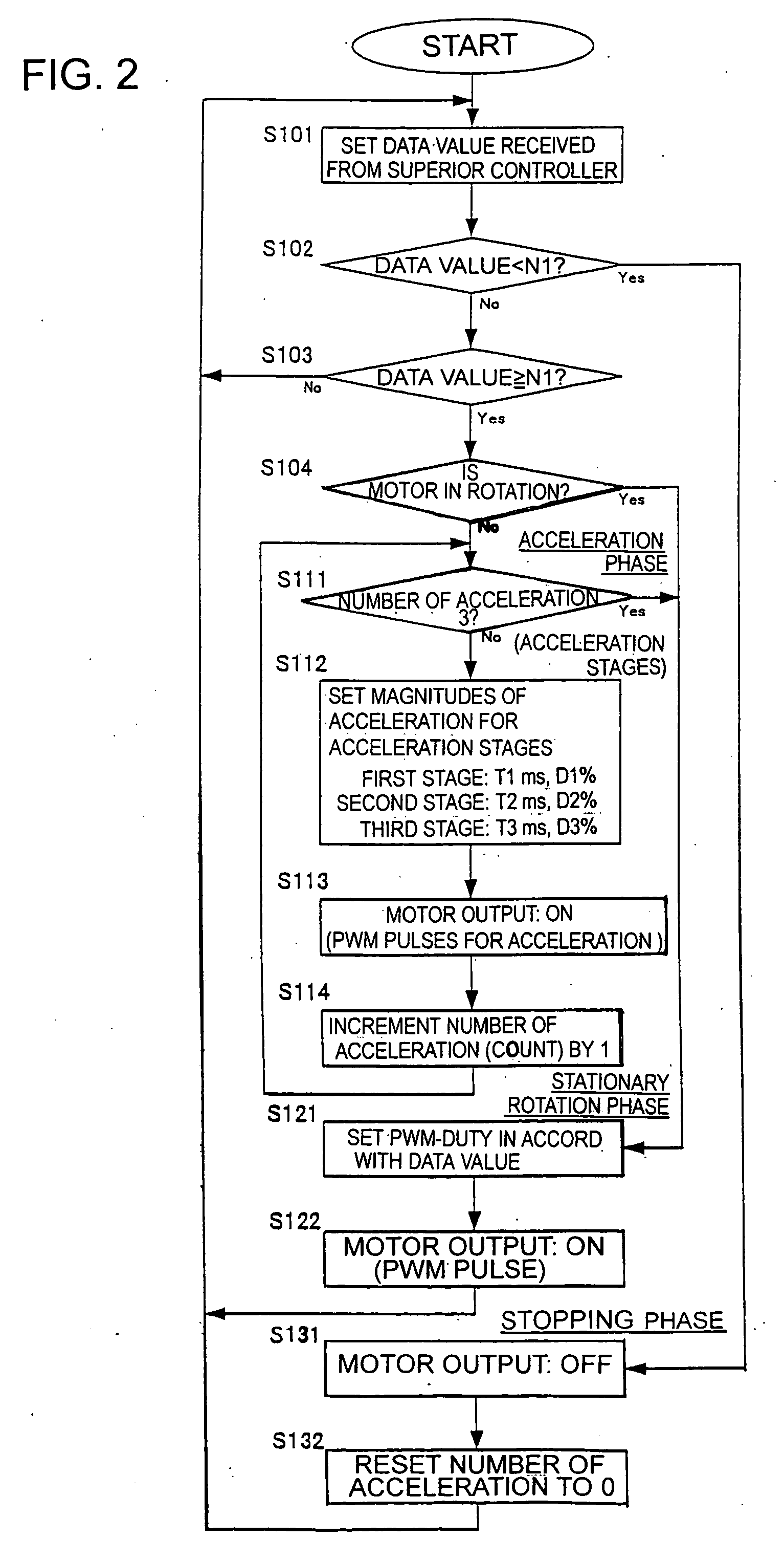
[0030] An inventive DC motor drive unit will now be described in detail by way of example with reference to the accompanying drawings. FIG. 1 is a block diagram showing a circuit arrangement of a DC motor drive unit 10 in accordance with one embodiment of the invention. FIG. 2 is a flowchart describing the operation of the circuit shown in FIG. 1. FIG. 3 shows an exemplary operative condition of the DC motor drive circuit shown in FIGS. 1 and 2.

[0031] The DC motor drive unit of FIG. 1 is controlled by an open loop control system. A DC motor 21 and a switching transistor 22 are connected between a power supply voltage Vcc and the ground. The switching transistor 22 has a base, which is supplied with PWM pulses Pwm from the motor drive control circuit 10 to turn on and off the switching transistor 22. An adjustment resistor 23 is a variable resistor for adjusting the base current of the transistor 22. The resistor 23 is provided as needed. A free wheel diode 24 is provided to restore...


PUM


Abstract

In a DC motor drive unit having an open loop control system, a judgment is made as to whether an externally supplied speed instruction data instructs driving of the DC motor or not, based on the speed instruction data itself. If a judgment is made that the speed instruction data instructs driving of the DC motor, a switching means (e.g. switching transistor) connected to the DC motor is controlled by PWM pulses having prescribed duty ratios over a predetermined acceleration period to accelerate the DC motor. After the acceleration period, the switching means is controlled by the PWM pulses having a duty ratio as instructed by the speed instruction data to drive the DC motor. This scheme permits suppression of the startup current of the motor, and hence reduction of the withstand current of the switching transistor, while ensuring secure startup of the motor. In addition, the range of controllable speed of the DC motor can be broadened.

Description

TECHNICAL FIELD [0001] This invention relates to a direct-current (DC) motor drive unit capable of securely starting up the motor with suppressed startup current and running the motor at the speed in accord with an external speed instruction. BACKGROUND ART [0002] Motors are used in game controllers and toys to drive or vibrate their moving parts. Mostly, DC motors are used for this purpose for the reason that they can be powered by batteries and their drive circuits are simple in structure. [0003]FIG. 5 shows a circuit arrangement of a widely used conventional DC motor drive circuit having an open loop control system. As shown in FIG. 5, a DC motor 1 is connected between a power supply voltage Vcc and the ground via a switching transistor 2 for switching on / off the motor. Since the speed of the DC motor 1 is proportional to the current I flowing through it, the DC motor 1 can be driven at a predetermined speed by controlling on-off operation of the switching transistor 2 using a dr...

Claims


Application Information

Patent Timeline
Patent Type & Authority Applications(United States)
IPC IPC(8): H02P7/29H02P1/18
CPCH02P7/29H02P1/18
Inventor SAITO, KOICHISATO, TOMOTAKE
Owner ROHM CO LTD
Why Eureka
Try Eureka