Dental drill device with a stop element

a stop element and drill bit technology, applied in dentistry, dental tools, medical science, etc., can solve the problems of inability to accurately define the actual drilling depth, unreadable handling, and soiled visual markings, and achieve the effect of reliable and simple handling

Inactive Publication Date: 2007-05-03
STRAUMANN HLDG AG
View PDF6 Cites 62 Cited by
  • Summary
  • Abstract
  • Description
  • Claims
  • Application Information

AI Technical Summary

Benefits of technology

[0015] In accordance with various embodiments of the present invention, a dental drill device is provided in which the position of the dr

Problems solved by technology

Those drills designed only with visual elements for determining the drilling depth have the disadvantage that, during use, the actual drilling depth cannot be defined with precision, and the visual markings can become soiled and thus unreadable.
In dental drill devices with a stop element, handling can p

Method used


Image

  • Dental drill device with a stop element
  • Dental drill device with a stop element
  • Dental drill device with a stop element

Examples


Embodiment Construction

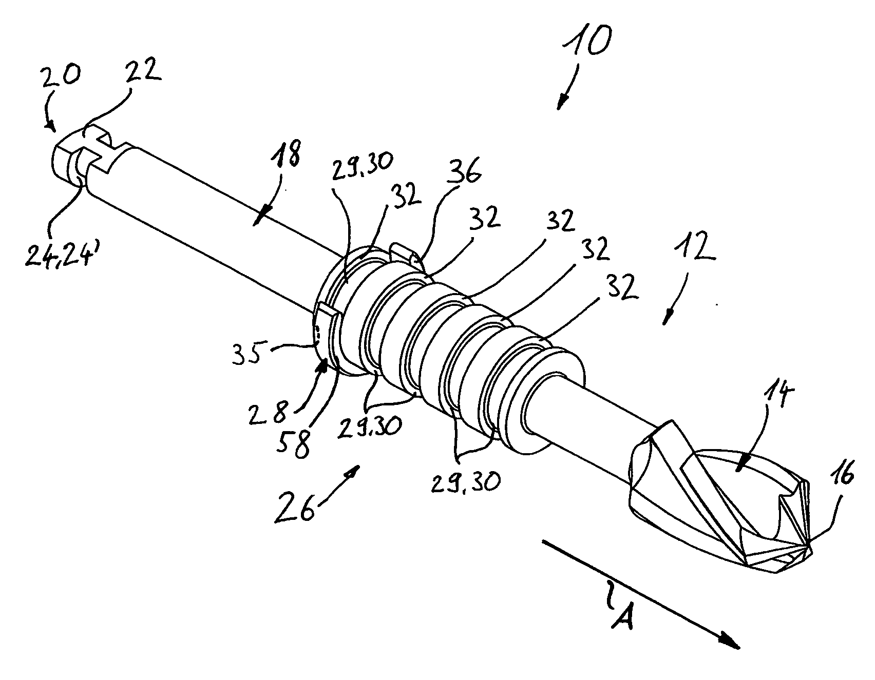
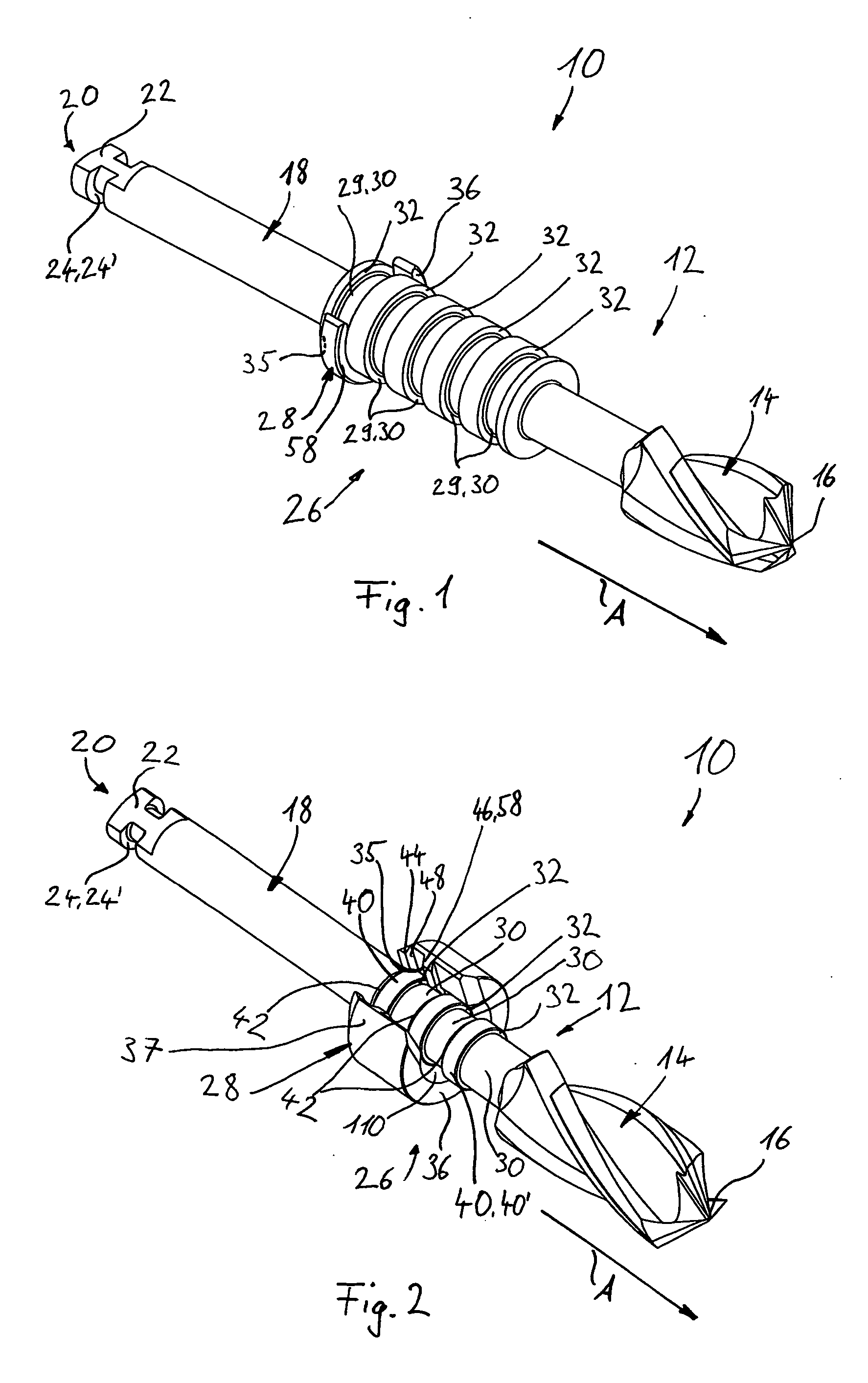
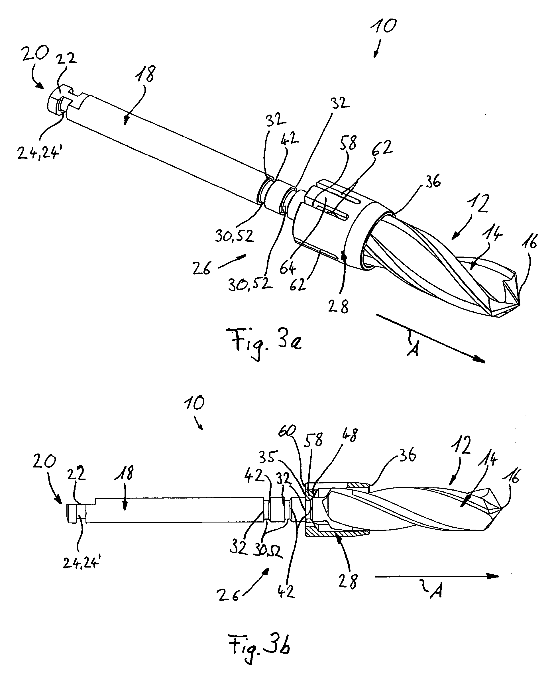
[0034]FIG. 1 shows a first illustrative embodiment of a dental drill device 10 according to the invention. A dental drill 12 has, at one end, a cutting part 14 with an exposed drill end 16, and, at the other end, a shank part 18 with an exposed receiving end area 20. The receiving end area 20 is intended to be received in a generally known drill holder device and has a rotation-preventing means 22 configured as a surface, and an axial securing means 24′ designed as a groove 24 extending partially in the circumferential direction. The rotation-preventing means 22 and the axial securing means 24′ means that the dental drill 12 can be brought into a fixed connection with the drill holder device, which for example is part of a drill drive or a hand drill.

[0035] The shank part 18 has a holder portion 26 for a stop element 28. This holder portion 26 is formed by a circular-cylindrical thickening of the shank part 18 into which five fastening recesses 30 designed as circumferential groove...


PUM


Abstract

Dental drill device (10) comprises a drill (12) with a stop element (28). In various embodiments, at one end, the drill (12) has a cutting part (14) with a free drill end (16) and, at the other end, it has a shank part (18). Arranged on the shank part (18) there is a holder portion (26) with several fastening recesses (30) spaced apart from one another in the axial direction (A), each fastening recess (30) being limited, in the direction of an exposed receiving end area (20) of the shank part (18), by an abutment surface (34) which is at right angles to the axial direction (A) of the drill (12). A stop element with a drill abutment (36) is fitted onto the holder portion (26) and has an engagement element (58). The engagement element (58) has a counter-abutment surface (35) which cooperates in a form fit with the abutment surface (32). By means of the form fit acting between the abutment surface (32) and the counter-abutment surface (35), the stop element (28) is held on the drill (12) such that it cannot be displaced in the direction of the receiving end area (20) of the drill (12).

Description

FIELD OF THE INVENTION [0001] The present invention relates to a dental drill device. BACKGROUND OF THE INVENTION [0002] U.S. Pat. No. 5,890,897 discloses a dental drill device with a stop element held on a drill. The stop element engages completely around the drill in the circumferential direction and is held on it so as to be displaceable in the axial direction. [0003] The drill has an exposed drill end on a cutting part, and a cylinder shank with an exposed shank end face. Located between the drill end and the shank end face there is a holder portion with several spherical-cap-shaped fastening recesses spaced apart from one another in the axial direction and oriented toward one another. [0004] The stop element has a circular-cylindrical shape with a drill abutment surface. In the axial direction, the stop element is designed with a central through-opening which corresponds substantially to a diameter of the drill. In the radial direction of the stop element, an insert opening run...

Claims


Application Information

Patent Timeline
IPC IPC(8): A61C3/02
CPCA61B2019/306A61C3/02A61C5/025A61C8/0089A61B2090/036A61C5/44
Inventor MULLER, DANIELEKENK, FRANK
Owner STRAUMANN HLDG AG
Why Eureka
Try Eureka