
Controller for controlling a plant

a plant and control device technology, applied in the direction of adaptive control, electric control, instruments, etc., can solve the problem of error between the output of the plant and a desired value, and achieve the effect of accurate control of the engine torque, and high accuracy

Active Publication Date: 2007-05-03
HONDA MOTOR CO LTD
View PDF7 Cites 4 Cited by
  • Summary
  • Abstract
  • Description
  • Claims
  • Application Information

AI Technical Summary

Benefits of technology

The solution effectively reduces engine vibration, stabilizes rotational speed, prevents stall during idling, and improves response during gear changes, enhancing the accuracy and robustness of engine torque control.

Problems solved by technology

An error between the output of the plant and a desired value for the output of the plant may be caused by disturbance applied to the plant.

Method used


Image

  • Controller for controlling a plant
  • Controller for controlling a plant
  • Controller for controlling a plant

Examples


Embodiment Construction

Structure of Internal Combustion Engine and Control Unit

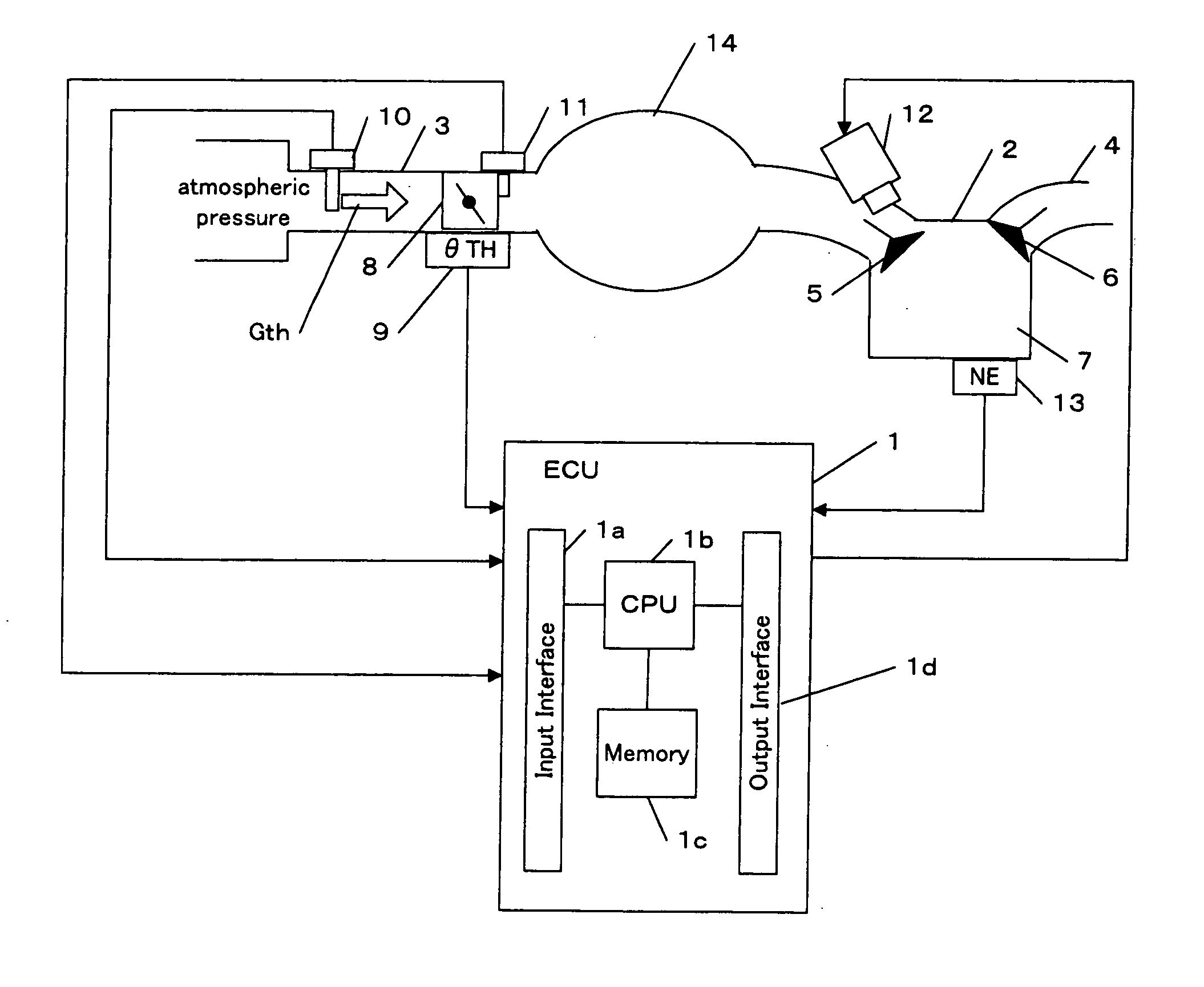
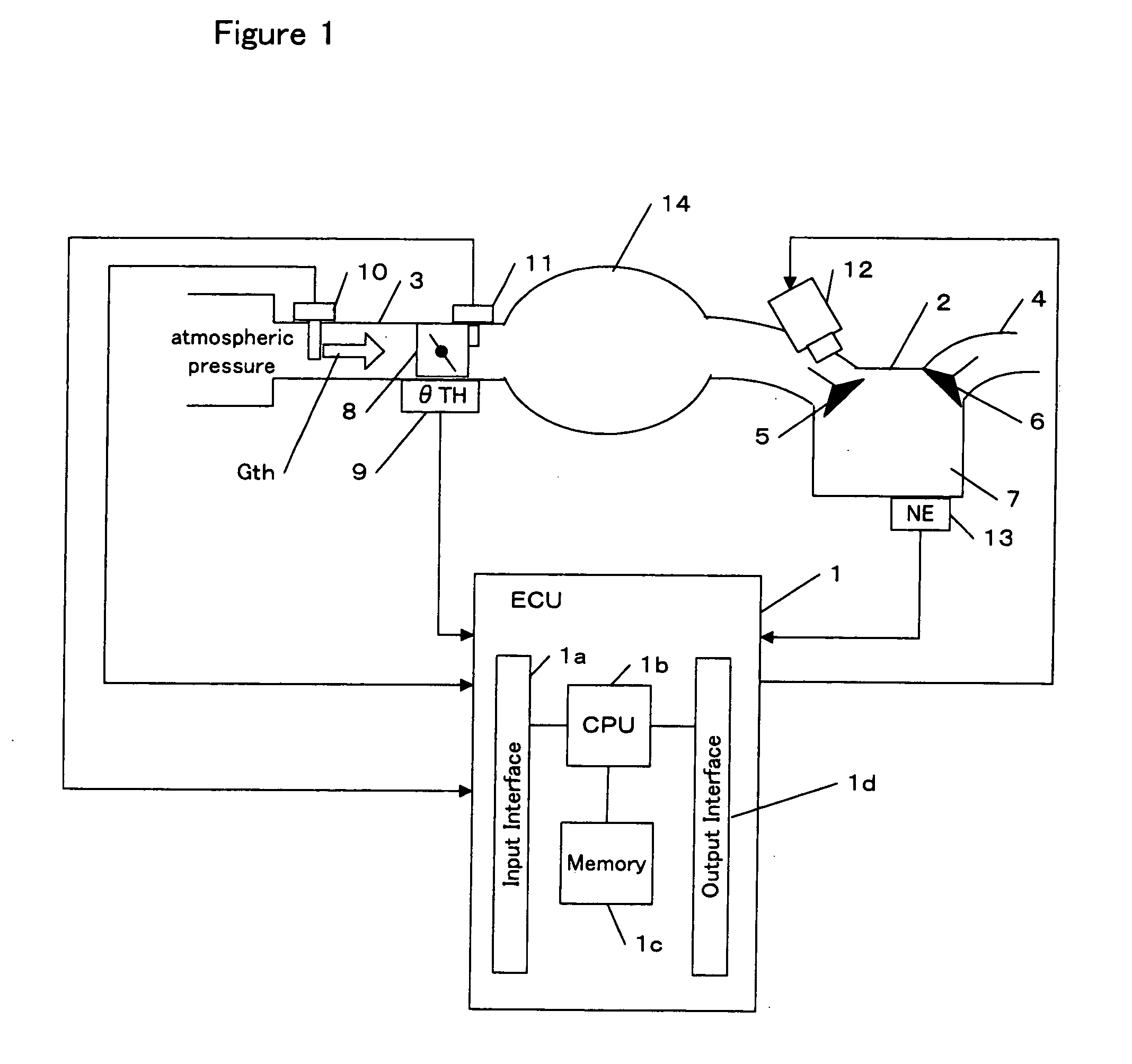
[0051] Referring to the drawings, specific embodiments of the invention will be described. FIG. 1 is a block diagram showing an internal combustion engine (hereinafter referred to as an engine) and its control unit in accordance with one embodiment of the invention.

[0052] An electronic control unit (hereinafter referred to as an ECU) 1 comprises an input interface 1a for receiving data sent from each part of the vehicle, a CPU 1b for carrying out operations for controlling each part of the vehicle, a memory 1c including a read only memory (ROM) and a random access memory (RAM), and an output interface 1d for sending control signals to each part of the vehicle. Programs and various data for controlling each part of the vehicle are stored in the ROM. The ROM may be a rewritable ROM such as an EEPROM. The RAM provides work areas for operations by the CPU 1b, in which data sent from each part of the vehicle as well as control si...


PUM


Abstract

The present invention provides a controller for controlling a modeled plant robustly against disturbance. The controller comprises an estimator and a control unit. The estimator estimates disturbance applied to the plant. The control unit determines an input to the plant so that an output of the plant converges to a desired value. The input to the plant is determined to include a value obtained by multiplying the estimated disturbance by a predetermined gain. Since estimated disturbance is reflected in the input to the plant, control having robustness against disturbance is implemented. The controller may comprise a state predictor. The state predictor predicts the output of the plant based on the estimated disturbance and dead time included in the plant. The control unit determined the input to the plant so that the predicted output converges to a desired value. Since the state predictor allows for the dead time, the accuracy of the control is improved. The estimated disturbance is reflected in the predicted output, an error between the predicted output and an actual output of the plant is removed.

Description

BACKGROUND OF THE INVENTION [0001] The present invention relates to an apparatus for robustly controlling a plant against disturbance. [0002] The amount of air introduced into an engine is typically controlled so as to achieve a desired engine torque. According to a conventional method, a desired amount of air introduced into the engine is determined referring to a map based on an opening angle of an accelerator pedal, a vehicle speed and a selected transmission gear ratio. An opening angle of a throttle valve is controlled in accordance with the desired amount of air to be introduced into the engine. [0003] According to another method disclosed in Japanese Patent No. 2780345, a desired torque of an engine output shaft is determined in accordance with an opening angle of an accelerator pedal and a rotational speed of the output shaft of a torque converter. A desired opening angle of a throttle valve is determined referring to a predetermined table based on an actual rotational speed...

Claims


Application Information

Patent Timeline
Patent Type & Authority Applications(United States)
IPC IPC(8): G06F17/00F02D11/10G06F19/00F02D9/02F02D41/14F02D45/00G05B13/02G05B13/04
CPCF02D41/1402F02D2041/1409F02D2041/1415F02D2041/1416F02D2041/1423F02D2041/1431
Inventor YASUI, YUJISHIMOJO, KANAKOHASHIMOTO, EIJIIWAKI, YSHIHISA
Owner HONDA MOTOR CO LTD
Learn More