Offset outlet flush valve and method for making same

a flush valve and outlet technology, applied in the field of flush valves, can solve the problems of limiting the overflow capacity of the flush valve, compromising the ability of the overflow tube to do its job, and ignoring the adequate overflow capacity, so as to improve the flow capacity, minimize the impact of the flapper valve bulb on the water flow continuum, and be readily adapted to the tank profile

Active Publication Date: 2007-05-10
LAVELLE IND
View PDF6 Cites 11 Cited by
  • Summary
  • Abstract
  • Description
  • Claims
  • Application Information

AI Technical Summary

Benefits of technology

[0009] Accordingly, a primary objective of the device of the present invention is to provide an offset outlet flush valve that provides improved flow capacity. It is another object to provide an offset outlet flush valve that can be used in original manufacture toilet fixtures as well as for the after market and that can be readily adapted to the tank profile of a wide variety of gravity operated flush toilets. It is still another object to provide an offset outlet flush valve that can be used with flapper valves of other manufacture such that impingement by the flapper valve bulb within the water flow continuum is minimized. It is yet another object of the device of the present invention to provide such an offset outlet flush valve that is easier to fabricate.
[0010] In accordance with the aforementioned objectives of the present invention, there is provided a flush valve having an offset outlet that provides better flow capacity, that is simpler to manufacture and that can be used as equipment in toilets of original manufacture and as replacement after-market devices. The foregoing and other features of the device and method of the present invention will be apparent from the detailed description that follows.

Problems solved by technology

In this configuration, the bulb of the flapper valve can severely restrict the overflow capacity of the flush valve by impinging on the flow area around the bulb, including the passageway between the overflow tube and the flush valve outlet.
The problem is that adequate overflow capacity is completely overlooked, because the only issue in the consumer's mind is typically how to stop the flapper from leaking.
If the passageway between the overflow tube and the flush valve outlet is blocked, even in part, by the flapper valve bulb, then the ability of the overflow tube to do its job is compromised.
The flush valve of prior art is also rather difficult to mold as a one-piece item using conventional plastic molding processes.
In the conventional molding process, complicated retracting mold cores are required to be used to form the passageway.
In the experience of these inventors, it would be unduly expensive to manufacture a variety of different overflow valves, each having an overflow tube of different height, to satisfy the configurations of the various gravity operated flush toilets manufactured in the United States and abroad.

Method used


Image

  • Offset outlet flush valve and method for making same
  • Offset outlet flush valve and method for making same
  • Offset outlet flush valve and method for making same

Examples


Embodiment Construction

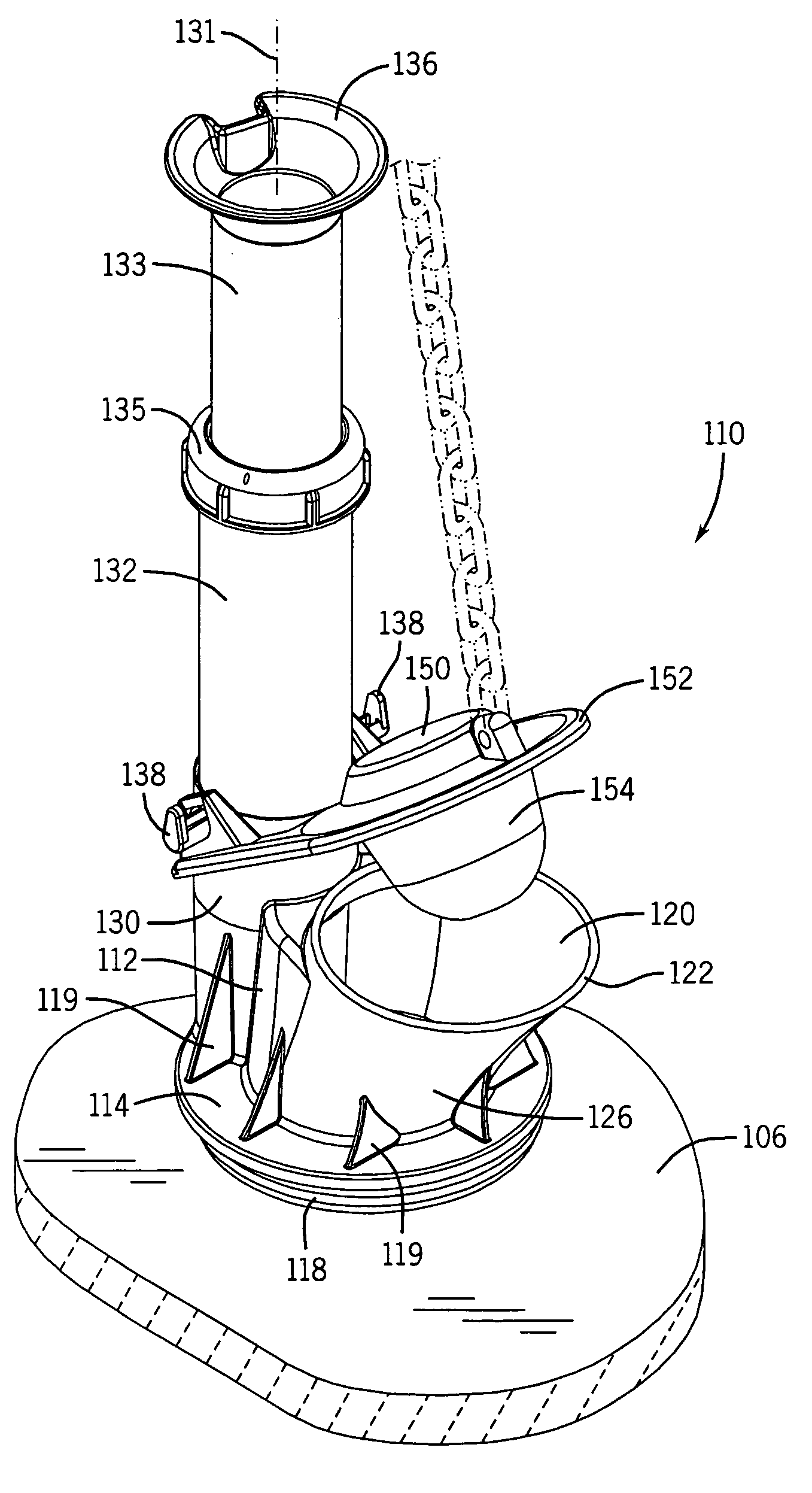
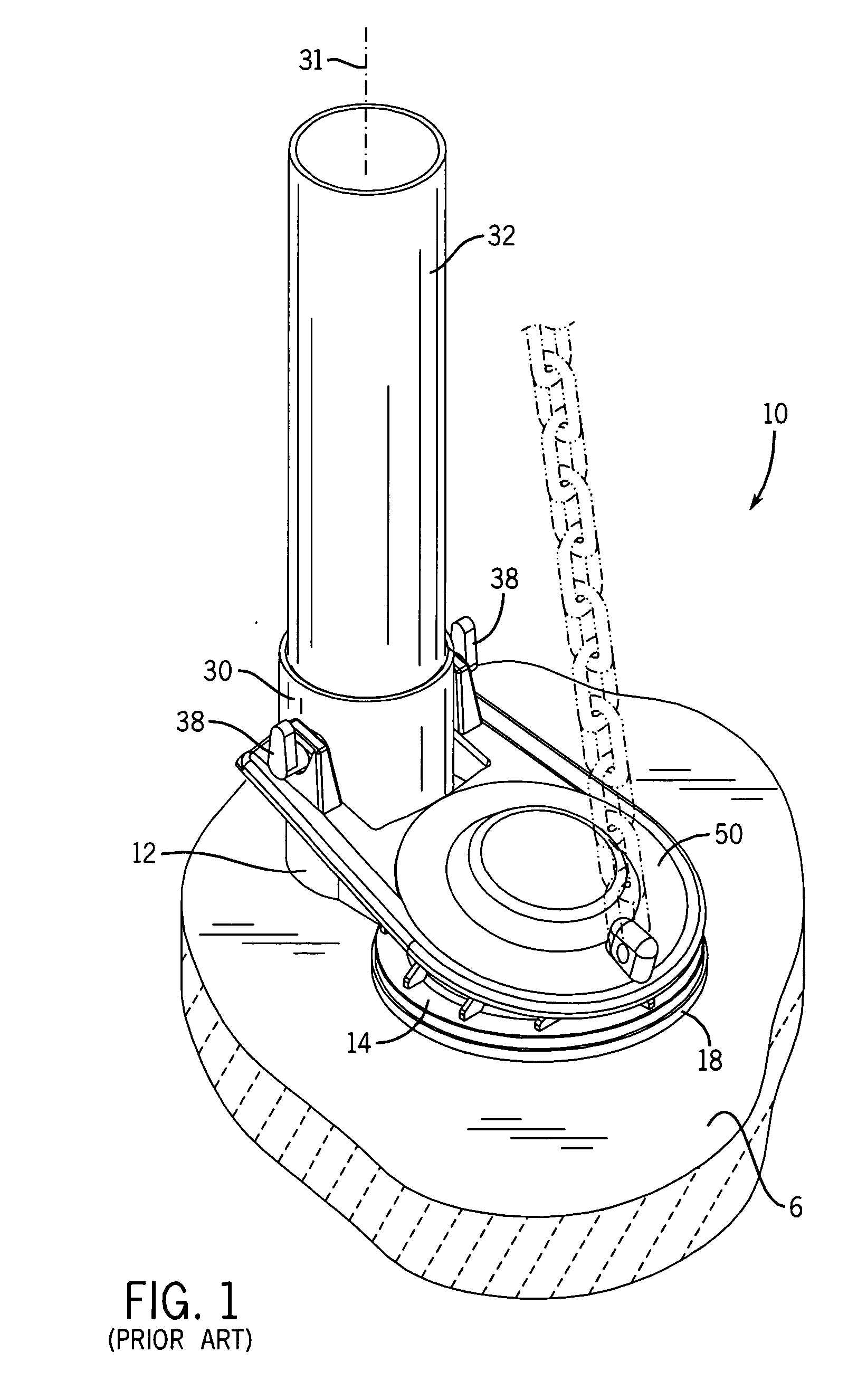
[0028] Referring now to the drawings in detail, wherein like-numbered elements refer to like elements throughout, FIGS. 1 through 5 illustrate a conventional flush valve, generally identified 10, of a type that is known in the art. The flush valve 10 includes a valve body 12 that has a generally cylindrical central aperture 20 with a round valve seat 22 upon which a liftable flapper valve 50 can be supported, the flapper valve 50 being rotatable about opposing hooks 38. The valve body 12 is secured within a drain hole 4 located in the bottom wall 6 of the toilet tank. The valve body 12 is supported by a flange 14. A seal member 18 is interposed between the flange 14 and the toilet tank wall 6. Typically, a large nut 16 (shown in phantom view in FIGS. 3 and 4) is screwed over a male threaded lower outlet portion 40 of the cylindrical flush valve body 12, on the underside of the bottom wall 6 of the tank. Extending upwardly from and to one side of the flush valve 12 itself is a cylind...


PUM


Abstract

An offset outlet flush valve has a valve body, the valve body having an inlet comprising an inlet aperture, an overflow tube socket comprising an overflow tube aperture, and an outlet comprising an outlet aperture. The outlet aperture of the valve body, and the wall that defines it, intersects a portion of the inlet aperture and a portion of the overflow tube aperture and the walls that define them. In this way, a water flow continuum is created between the inlet aperture and the outlet aperture and between the overflow tube aperture and the outlet aperture. A number of alternative embodiments of an overflow tube socket and overflow tube are also provided depending upon OEM or after-market application of the offset outlet flush valve.

Description

FIELD OF THE INVENTION [0001] The present invention relates generally to plumbing fixtures and to the component parts that are used in them. More particularly, it relates to a flush valve for use in a toilet tank that has a valve body where the flush valve outlet is offset whereby improved flushing capacity and improved overflow capacity is realized and manufacture of the valve body is simplified. It also relates to such a valve body that can be configured for use in original toilet plumbing as provided by a manufacturer or as a replacement item for use in a wide variety of toilet tanks and fixtures as an after-market installed flush valve. BACKGROUND OF THE INVENTION [0002] A conventional gravity operated flush toilet has several basic components. The china components include a bowl and a tank mounted atop a rear portion of the bowl. The bowl and tank may either be separate pieces or may be molded as a single unitary piece. The plumbing components of the conventional gravity operat...

Claims


Application Information

Patent Timeline
Patent Type & Authority Applications(United States)
IPC IPC(8): E03D1/35
CPCE03D1/306
Inventor TORRES, ALBERTO C.NICHOLS-ROY, DAVIDWOODS, DENNIS D.
Owner LAVELLE IND
Why Eureka
Try Eureka