Cleat for athletic shoe

a technology for athletic shoes and cleats, applied in the field of athletic cleats, can solve the problems of only minimal bracing of cleats, little to counter the above-described and each difficulty, so as to prevent the rotational movement of golfers' feet

Inactive Publication Date: 2007-05-10
PEAKE FREDERICK B
View PDF29 Cites 32 Cited by
  • Summary
  • Abstract
  • Description
  • Claims
  • Application Information

AI Technical Summary

Benefits of technology

[0016] In use, a golfer's shoe is in contact with any commonly encountered ground surface mentioned above. When a golfer prepares to swing a golf club he will firmly plant his feet on the ground. At this point the distal ends of the plurality of barbs on the golf cleat will pierce the ground surface below. The distal end is generally a point, but all that is required is that the distal end is narrower than the proximal end of each barb. Therefore, it is easier for the barb to slide into the ground surface below given its relatively narrow distal end and wider proximal end. Once engaged and as the golfer begins the backswing, the rear foot will experience the rotational forces mentioned above. As a result of this rotation, the perpendicular surface of the plurality barbs will be forced against the ground. Furthermore, the angled surface of the barbs allows the golf cleat to dig deeper into the ground during rotation, which in turn provides more resistance in the perpendicular surface. Preferably, the barbs deflect very little during this process and therefore provide adequate resistance to the rotational forces associated with a golf swing. The rotational forces encountered in the front foot during the downswing and follow through are also resisted primarily by the perpendicular surface of the plurality of barbs in this same manner. Importantly, as a cleat system it is configurable to be readily retrofitted to any golf shoe available with a simple change of cleats.
[0020] In still another embodiment, the invention is a golf cleat system. A left shoe has a bottom sole and a plurality of removable golf cleats connected to the bottom sole. Each golf cleat has a plurality of barbs that are preferably all oriented to resist counterclockwise rotation of the shoe. A right shoe has a bottom sole and a plurality of golf cleats connected to the bottom sole. Each golf cleat has a plurality of barbs that are configured and oriented to resist clockwise rotation of the shoe. Together, the shoes prevent rotational movement of a golfer's foot during a golf swing. These golf cleats may also be made from an elastomeric material

Problems solved by technology

A proper golf swing requires a good foundation, stability and balance, each of which is made more difficult due to the great deal of rotational movement in the body of a golfer.
Unfortunately, however, known soft spike-type cleats provide only minimal bracing, as the cleats often times “roll over” or otherwise give as the torque of the golfer's body during a swing exerts forces thereon, as described further below.
However, extending substantially entirely orthogonally to the sole of the shoe, such spikes do little to counter the above-described rotational movement of the golfer's feet.
Moreover, these metal spikes often leave spike marks behind causing excessive damage to the golf course, especially the greens.
Therefore, though providing generally adequate bracing capabilities, a great deal of effort has gone into developing alternative material spikes that provide improved bracing capabilities while minimizing the divots left behind.
These spikes have provided some bracing capabilities, and are more green friendly, but generally lack stiffness.
Specifically, as noted previously, such spikes have a tendency to “roll-over” during play, and therefore do not adequately counter rotational movement of a golfer's foot.
Moreover, as a result, the spikes often break or fray and thus have to be replaced all too frequently.
Grass and mud often get caught in the spikes, especially as they roll over, thus causing the bracing provided by the shoes to be further compromised.
With respect to harder surfaces, they have a tendency to wear down rubber spikes more quickly.
For example, cement is likely the most damaging surface and it is often encountered when the golfer is entering and leaving the course.
However, many of these spikes have blunt, bulky barbs that are unable to penetrate the plethora of surfaces encountered on a golf course.
In sum, these spikes cannot provide adequate resistance to the rotational movement of a golfer's feet associated with a golf swing.

Method used


Image

  • Cleat for athletic shoe
  • Cleat for athletic shoe
  • Cleat for athletic shoe

Examples


Embodiment Construction

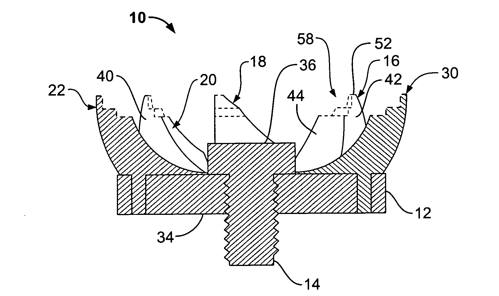
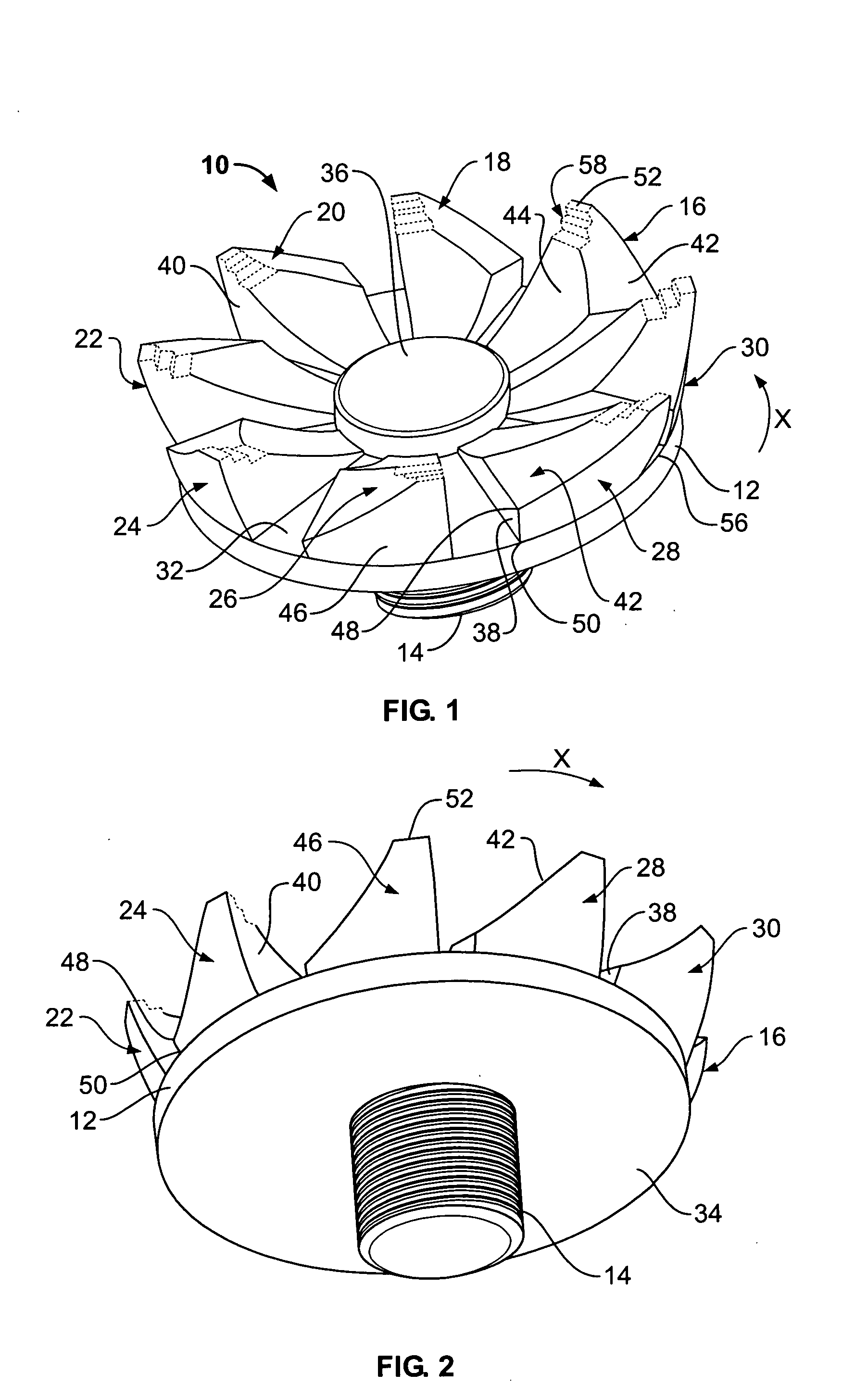
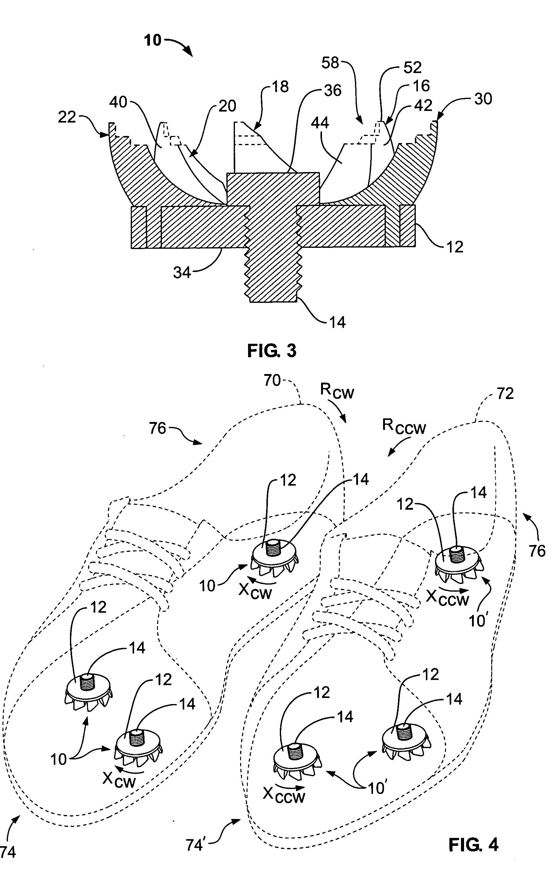
[0028] A golf cleat 10 according to one preferred embodiment of the invention is shown in FIGS. 1-3. The golf cleat 10 preferably includes a base 12, a threaded screw 14, and, in this embodiment, eight barbs 16, 18, 20, 22, 24, 26, 28, 30. The base 12 has two oppositely opposed surfaces, the ground surface 32 and the back surface 34. The threaded screw 14 is preferably attached to the back surface 34. This allows a user to removably secure the golf cleat 10 into a threaded receiving hole in the bottom sole of a shoe (not shown), for ready replacement of the cleats with any conventional golf shoe.

[0029] The eight barbs 16-30 are connected to the ground surface 32 and centered around a hub 36. Each barb 16-30 is identical and therefore it is understood that a description of one barb 16 is sufficient to describe all barbs 16-30. Barb 16, best seen in FIGS. 1 and 4, preferably has a minor surface, the rear surface 38, and four main surfaces, the perpendicular surface 40, the angular su...


PUM


Abstract

A golf cleat and system includes cleats having a base and a plurality of barbs. Each barb preferably has a proximal end supported by the base and a distal end extending generally perpendicular from the base. A perpendicular surface is formed by the distal end extending from the base and preferably counters rotational movement of a shoe in a plane generally parallel to the ground during a golf swing. At least some of the barbs preferably have an angular surface between the distal end and the base.

Description

BACKGROUND OF THE INVENTION [0001] 1. Field of Invention [0002] The present invention is directed to apparatus for improving traction, balance and stability during a golf swing, and more particularly, a cleat for attachment to the sole of a golf shoe configured to resist the rotational movement of a golfer's foot during a swing. [0003] 2. Description of Related Art [0004] The game of golf presents participants with a unique mixture of challenge and recreation. Overall, golf is widely embraced by the international population and there is a continual desire to overcome the challenges inherent in the game thus increasing a golfer's enjoyment of the sport. [0005] With an ever increasing population of golfers, professional and recreational alike, the sophistication of golf equipment has grown by leaps and bounds all in an effort to simplify this difficult sport. Golf clubs have taken advantage of different materials, such as graphite, and shapes to increase power and accuracy. Golf balls...

Claims


Application Information

Patent Timeline
Patent Type & Authority Applications(United States)
IPC IPC(8): A43B5/00
CPCA43B3/0094A43B5/001A43C15/162
Inventor PEAKE, FREDERICK B.
Owner PEAKE FREDERICK B
Why Eureka
Try Eureka