Ejector mechanism for back hoe excavator bucket

a back hoe and bucket technology, applied in mechanical machines/dredgers, soil shifting machines/dredgers, construction, etc., can solve the problems of not being removed, exacerbated problems, and effective operation, and achieve the effect of simple mechanical linkage and less adhesion of material

Inactive Publication Date: 2007-05-10
ARP REGIS L
View PDF1 Cites 10 Cited by
  • Summary
  • Abstract
  • Description
  • Claims
  • Application Information

AI Technical Summary

Benefits of technology

[0015] A further object is to provide such an ejector mechanism that has a relatively small surface area contacting material in the excavator bucket to be unloaded to substantially lessen the amount of adhesion of the material in the bucket with the ejector mechanism.
[0016] A further object is to provide such an ejector mechanism that has simple mechanical linkages that allow the mechanism to be retrofitable on many existing excavator buckets of various manufacturers as well as being installable in new buckets in the manufacturing process.
[0018] Yet another object is to provide such an ejector mechanism that is of new and novel design, of a rugged and durable nature, of simple and economic manufacture and one that is otherwise well-suited to the uses and purposes for which it is intended.

Problems solved by technology

This operation is effective, however, only with loose granular non-cohesive materials such as particulated rock, sand, dry soils, small debris and the like.
If material being excavated is adhesive to adhere to the surface of the carrying excavator bucket, it often may not be removed from the excavator bucket solely by force of gravity and requires other means to remove it.
This problem is exacerbated if the material is also cohesive.
The problem of cohesiveness is common with soil materials consisting of, or containing, wet clay, various finely particulated soil materials or debris containing wet clay or other material that is both cohesive and adhesive.
These solutions however are labor intensive, time consuming, not cost efficient and the machine activated pounding process may cause damage to the excavator bucket or the mechanism associated with it.
None of such methods, however, have completely or adequately resolved the problems, at least for all or a substantial number of the excavator buckets of modern commerce and the various materials causing adhesion and cohesion.
This solution is not efficiently operative and, if it is operative at all, generally requires substantial power in addition to gravity force to remove material from the excavator bucket.
By reason of the substantial power requirement for operation of the extractor plate, many such mechanisms have been powered by new hydraulic linkages that were not originally provided with a back hoe and, if mechanically activated, such linkages have required complex power magnifying linkages which have not proven to be well or efficiently operative, have been short lived and have required substantial maintenance.
Such multiple band-like devices have generally been complex, have been adapted for use only with particular excavator buckets and in use have not proven to be particularly efficient or effective in removing all or substantial amounts of contained material from the excavator buckets they service.
Various such systems have continued to suffer the mechanical problems associated with the large plate devices, have not been easily retrofitable on pre-existing machines they service and have required complex mechanical linkages that use substantial force to accomplish their motion.
The complexity of such more modern cleaning systems generally has required such modification of excavator buckets, their ordinary mechanical linkages, or both as to require the ejector mechanism to be created during the manufacture of the excavator bucket and generally make impractical the retroactive installation of the systems in existing extractor buckets and their moving mechanisms, at least by ordinarily skilled mechanics in the art.
The ejector arms yet provide quite sufficient area to eject material from the excavator bucket when in unloading position, but not enough area to allow adhesion of any substantial amount of material in the excavator bucket.

Method used


Image

  • Ejector mechanism for back hoe excavator bucket
  • Ejector mechanism for back hoe excavator bucket
  • Ejector mechanism for back hoe excavator bucket

Examples


Embodiment Construction

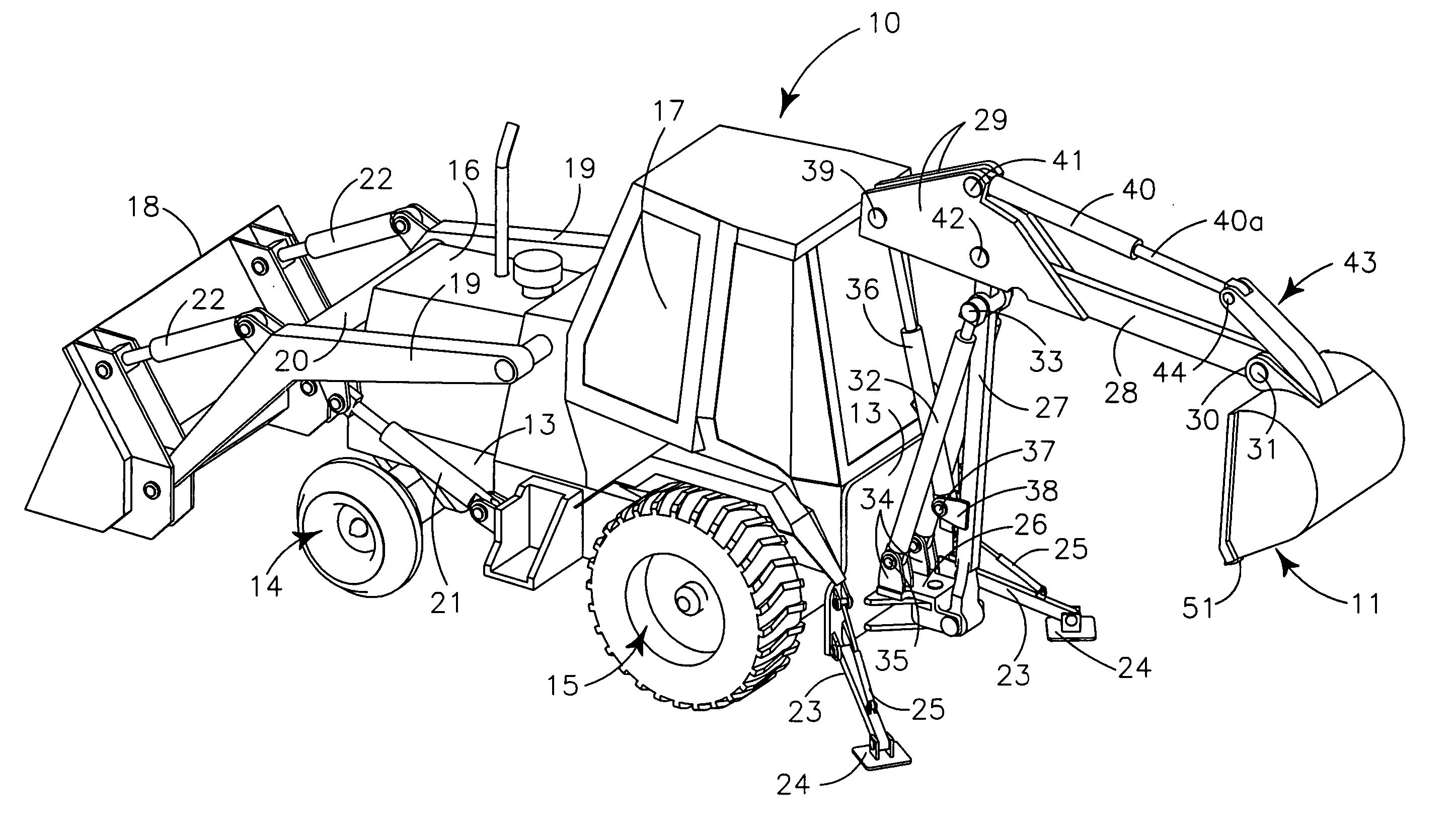
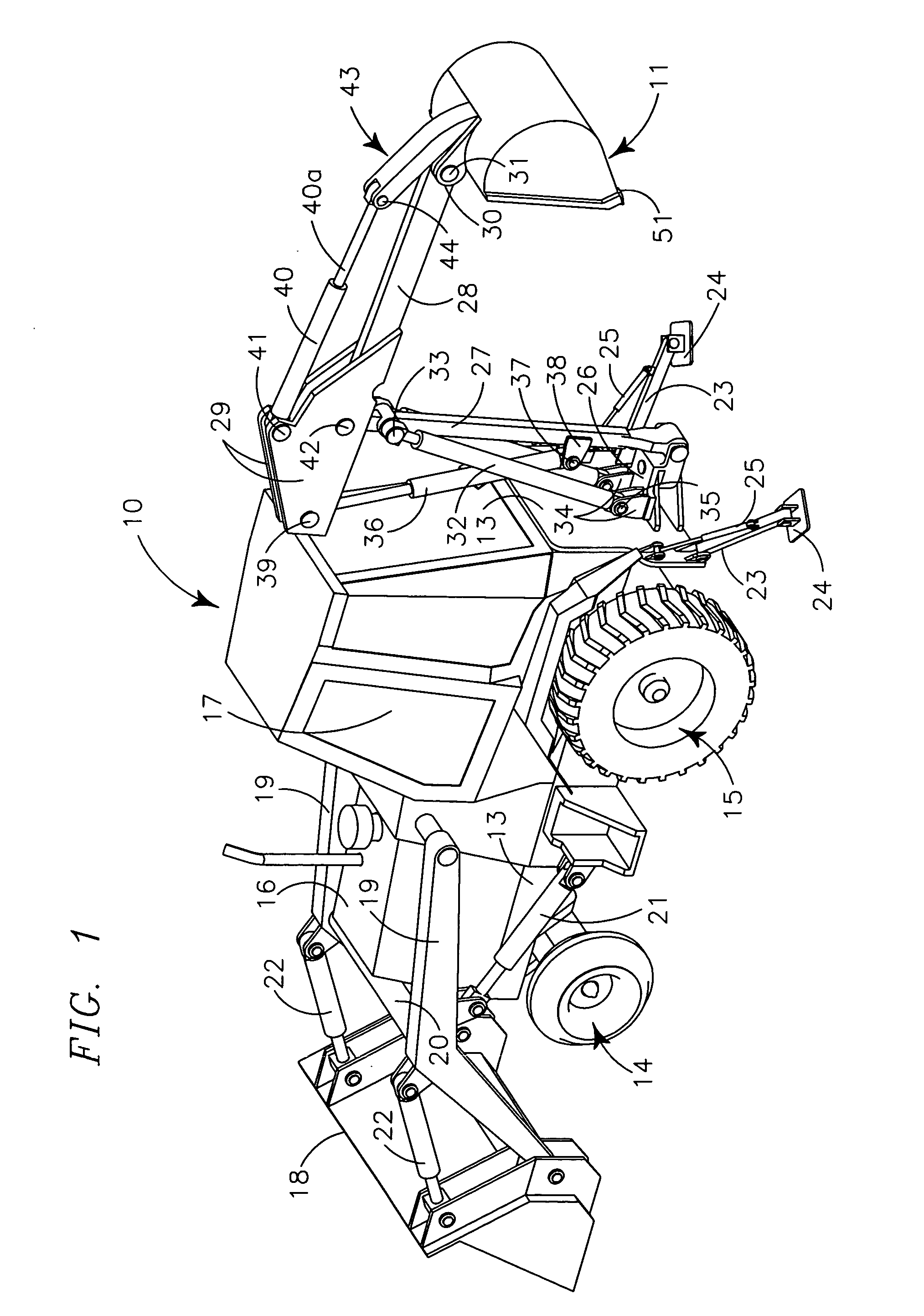
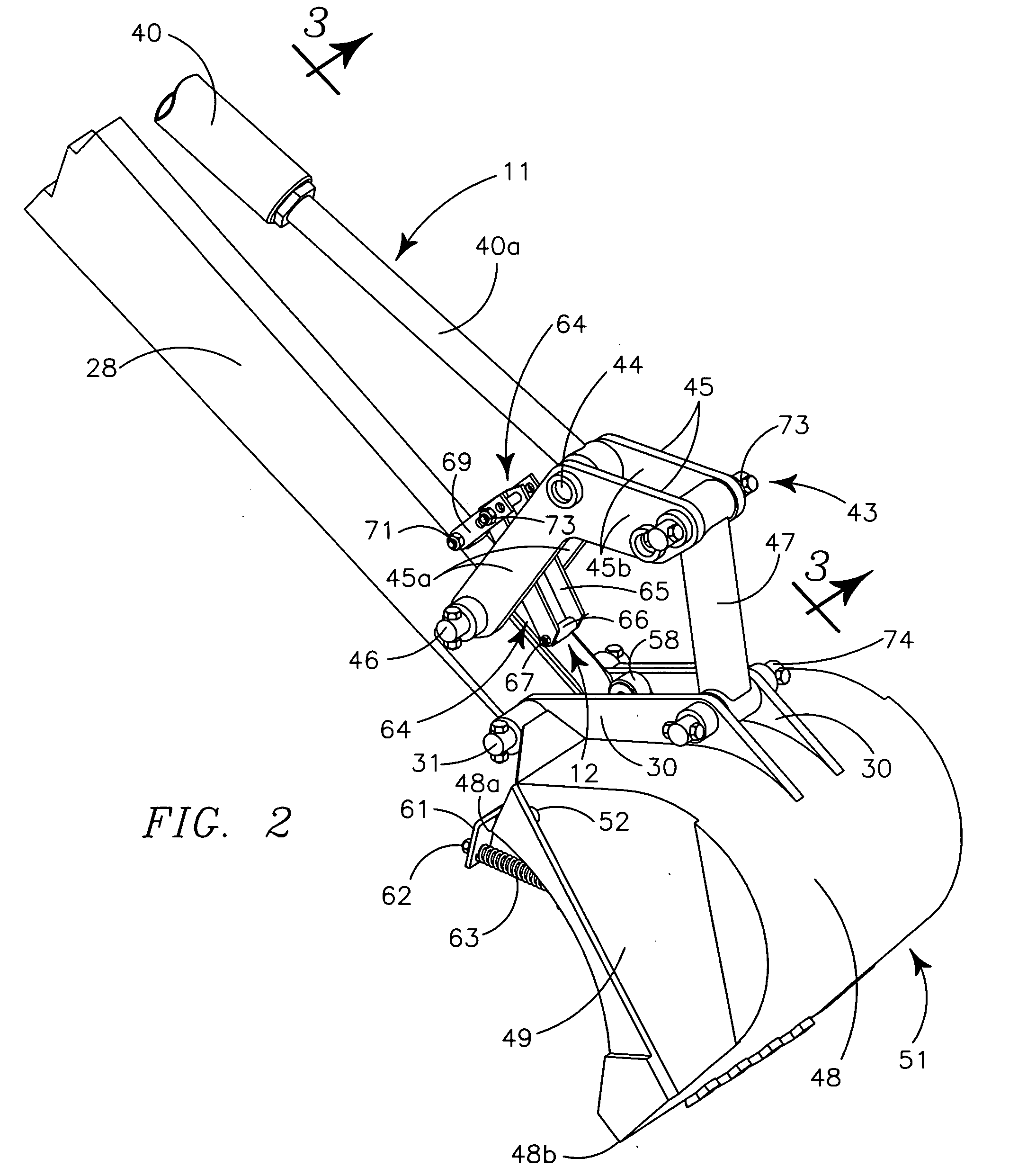
[0034] My invention generally provides ejector mechanism 12 in a first species and ejector mechanism 12A in a second species, both for use on a back hoe vehicle 10 having excavator bucket mechanism 11. The term “ejector arm shaft” as used herein refers to an ejector arm axle and a tubular sleeve carried by an ejector arm axle.

[0035] A somewhat generically illustrated back hoe, typical of such machines in the present day marketplace produced by various manufactures, is illustrated in FIG. 1. The back hoe vehicle 10 provides frame 13, supported on forward steerable wheel truck 14 and rearward driving wheel truck 15, and which in turn support motor structure 16 in its forward portion and operator cab 17 in its rearward portion. The forward portion of the back hoe vehicle 10 mounts larger load moving bucket 18 pivotally carried by similar laterally spaced angulated load moving bucket arms 19 pivotally supported on the upper elongately medial portion of frame 13. The load moving bucket ...


PUM


Abstract

Ejector mechanism for the excavator bucket of a back hoe provides two laterally spaced ejector arms irrotably carried on an ejector arm shaft journaled in horizontal orientation in the chamber of the excavator bucket to fit against the back and adjacent the sides of the bucket and pivot away from the back. A laterally medial powering arm irrotatably carried by the ejector arm shaft communicates through the back and extends forwardly to move upon an angulated ramp carried by the bucket tilting arm mechanism to pivot the ejector arms away from the back of the bucket as the bucket is tilted to a horizontal dumping position. The powering arm shaft is spring biased to maintain the ejector arms adjacent the bucket back when the bucket chamber is empty. The mechanism is retrofitable on various back hoe buckets of present day commerce.

Description

IIA. RELATED APPLICATIONS [0001] There are no applications related hereto heretofore filed in this or in any foreign country. II. BACKGROUND OF INVENTION [0002] IIB. Field of Invention [0003] This invention relates generally to material handling and more particularly to a load ejector for the excavator bucket of a back hoe that operates automatically responsive to positioning of the excavator bucket. [0004] IIC. Background and Description of Prior Art [0005] Back hoe excavator buckets and similar buckets on other digging machines pivotally mounted on a supporting beam for motion between somewhat vertical digging positions and somewhat horizontal unloading positions have long been known, are widely used in earth moving and are somewhat standardized in their structure and configuration. These excavator buckets in general have an open front that is pivoted to a vertical orientation to move horizontally through the earth to collect a load of material in the excavator bucket which is the...

Claims


Application Information

Patent Timeline
Patent Type & Authority Applications(United States)
IPC IPC(8): E02F3/96
CPCE02F3/407E02F3/425
Inventor ARP, REGIS L.
Owner ARP REGIS L
Why Eureka
Try Eureka