Method for designing a cryogenic air separation plant

a technology for air separation and cryogenic air, which is applied in the direction of refrigeration and liquid storage, lighting and heating equipment, solidification, etc., can solve the problems of increasing the overall cost of the plant beyond the equipment and construction costs, and the design of the cryogenic air separation plant is a complicated and thus costly endeavor

Inactive Publication Date: 2007-05-10
PRAXAIR TECH INC
View PDF8 Cites 16 Cited by
  • Summary
  • Abstract
  • Description
  • Claims
  • Application Information

AI Technical Summary

Benefits of technology

[0009] As used herein the term “engineered component” means a fully designed unit that performs at least one process step that is part of an overall process comprising heat exchange, distillation, compression and/or purification. Examples of engineered components include feed pretreat

Problems solved by technology

A cryogenic air separation plant is a very complicated process plant which includes many different units and subsystems such as distillation columns, condensers, reboilers, prepurification systems, air compression systems, liquid pumps, heat exchangers, storage tanks, process control systems, buildings and other infrastructure.
Accordingly, the designing o

Method used


Image

  • Method for designing a cryogenic air separation plant
  • Method for designing a cryogenic air separation plant
  • Method for designing a cryogenic air separation plant

Examples


Embodiment Construction

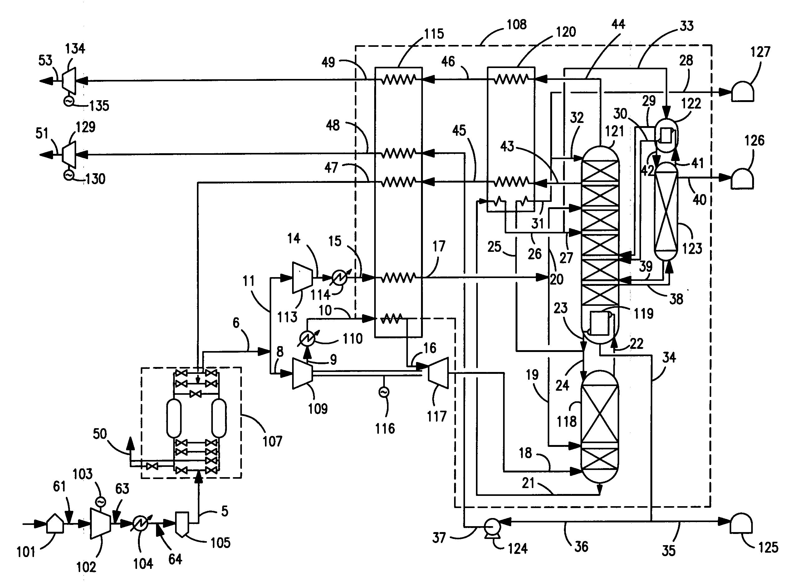
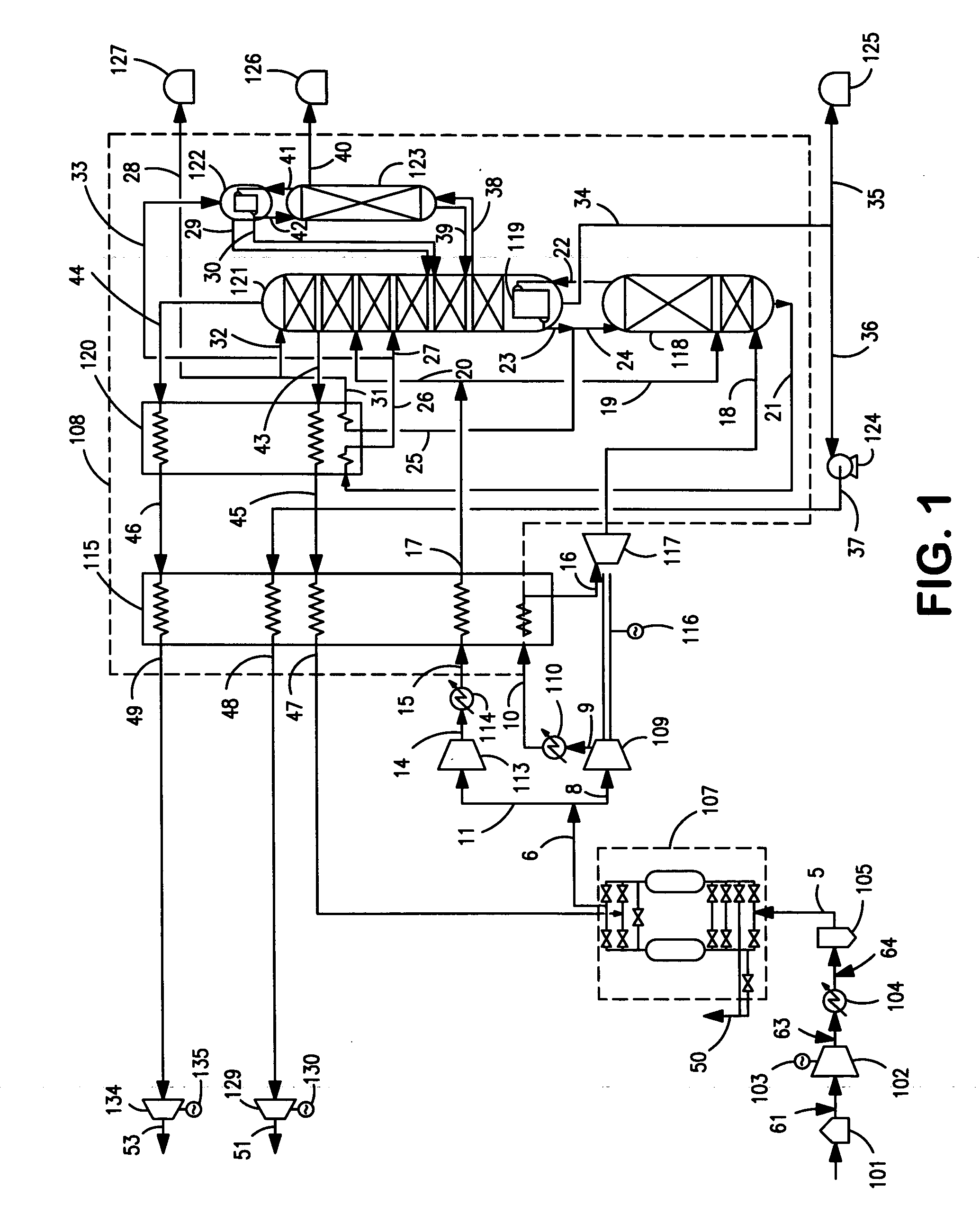
[0016] In the method of this invention cryogenic air separation plant classifications based on specific requirements such as plant size, i.e. capacity, product slate (oxygen, nitrogen, argon and / or clean dry air, etc.), product type (gas and / or liquid), product specification (purity and / or pressure) and location (back-up needs, ambient conditions, local factors etc.), are defined. The desired cryogenic air separation plant fits into one of the classifications and is designed by fitting together at least one predesigned subsystem for that classification with one or more subsystems specifically designed for that particular cryogenic air separation plant.

[0017] In the practice of this invention a base system is defined to comprise at least one, preferably two or more, predesigned subsystems that are common to meet different requirements regarding, for example, product type and purity. An auxiliary system is defined to comprise one or more subsystems that are designed specifically to p...


PUM


Abstract

A method for designing a cryogenic air separation plant wherein a particular plant which fits into a certain classification is designed by first employing at least one predesigned subsystem for that classification to form a base system and then completing the design by adding to the base system at least one auxiliary subsystem designed specifically for that particular plant.

Description

TECHNICAL FIELD [0001] This invention relates generally to cryogenic air separation and, more particularly,. to designing a cryogenic air separation plant. BACKGROUND ART [0002] A cryogenic air separation plant is a very complicated process plant which includes many different units and subsystems such as distillation columns, condensers, reboilers, prepurification systems, air compression systems, liquid pumps, heat exchangers, storage tanks, process control systems, buildings and other infrastructure. Accordingly, the designing of a cryogenic air separation plant is a complicated and thus costly endeavor which adds significantly to the overall costs of the plant beyond the equipment and construction costs. This is because in most cases each particular cryogenic air separation plant must be specifically designed. Rarely will an existing design for a previously constructed cryogenic air separation plant be exactly suited for use in the construction of a new cryogenic air separation p...

Claims


Application Information

Patent Timeline
IPC IPC(8): F25J3/00
CPCF25J3/0409F25J3/04296F25J3/04381F25J3/04412F25J3/04678F25J3/0489F25J2230/22F25J2290/10
Inventor SCHAUB, HERBERT RAYMONDSKARE, TODD ALANFASSBAUGH, JOHN HARRYMAY, DOUGLAS HENRYSPRIGGS, SCOTT ALAN
Owner PRAXAIR TECH INC
Why Eureka
Try Eureka