Digital log amplifier for ultrasonic testing

a digital log amplifier and ultrasonic testing technology, applied in the field of digital log amplifier for ultrasonic testing, can solve the problems of small signal very difficult to detect, analog amplifiers are not particularly well suited to perform, analog techniques are limited by noise and accuracy, etc., and achieve wide dynamic response range, high signal attenuation, and wide dynamic response range

Active Publication Date: 2007-05-10
GE INSPECTION TECH LP
View PDF23 Cites 4 Cited by
  • Summary
  • Abstract
  • Description
  • Claims
  • Application Information

AI Technical Summary

Benefits of technology

[0009] Another advantage of the present invention is that simultaneous reflected waveforms can be measured and recorded having a wide dynamic response range with no distortion of the respective waveforms.
[0010] Yet another advantage of the present invention is that a wide dynamic response range is provided for the measurement of signals reflected from various depths in a material characterized by high signal attenuation.
[0011] Other features and advantages of the present invention will be apparent from the following more detailed description of the preferred embodiment, taken in conjunction with the accompanying drawings which illustrate, by way of example, the principles of the invention.

Problems solved by technology

The large difference in amplitude of the two simultaneous signals makes the smaller signal very difficult to detect.
Previously, analog logarithmic amplifiers have been used in attempts to compress the dynamic response range, but analog amplifiers are not particularly well suited to perform this due to the limited bandwidth and dynamic response range of analog logarithmic amplifiers.
Analog techniques are limited by noise and accuracy problems.

Method used


Image

  • Digital log amplifier for ultrasonic testing
  • Digital log amplifier for ultrasonic testing
  • Digital log amplifier for ultrasonic testing

Examples


Embodiment Construction

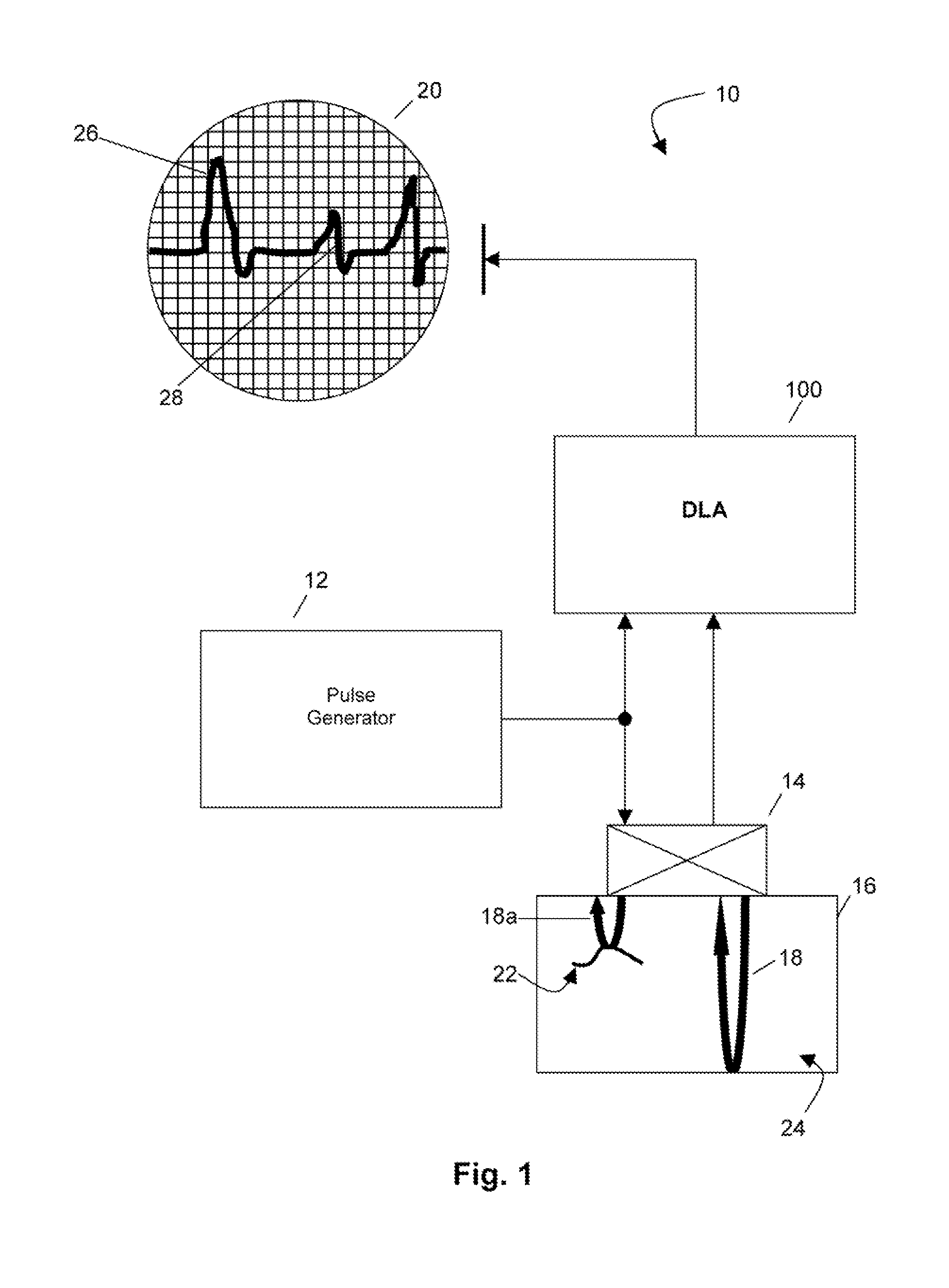
[0016] Referring to FIG. 1, a test inspection arrangement 10 includes a pulse generator circuit 12 that transmits a pulse to a transducer 14 for propagating an ultrasonic acoustic wave 18 through a test object 16. Wave 18 is reflected back to the transducer 14. In the example shown in FIG. 1, one transducer both transmits and receives the acoustic wave, however, other test configurations may also be employed with multiple transducers, some that transmit, some that receive, and some that perform both transmitting and receiving functions. The transducer 14 receives the reflected acoustic wave and converts it back into an electrical signal, which is input to the digital log amplifier (DLA) 100 of the present invention. The DLA 100 processes the electrical signal representing the reflected waveform, as discussed in further detail below. The output waveform of the DLA 100 is displayed on an oscilloscope 20 or other similar peripheral display or storage device (not shown). Many other test...


PUM

PropertyMeasurementUnit
frequencyaaaaaaaaaa
frequencyaaaaaaaaaa
physical propertiesaaaaaaaaaa

Abstract

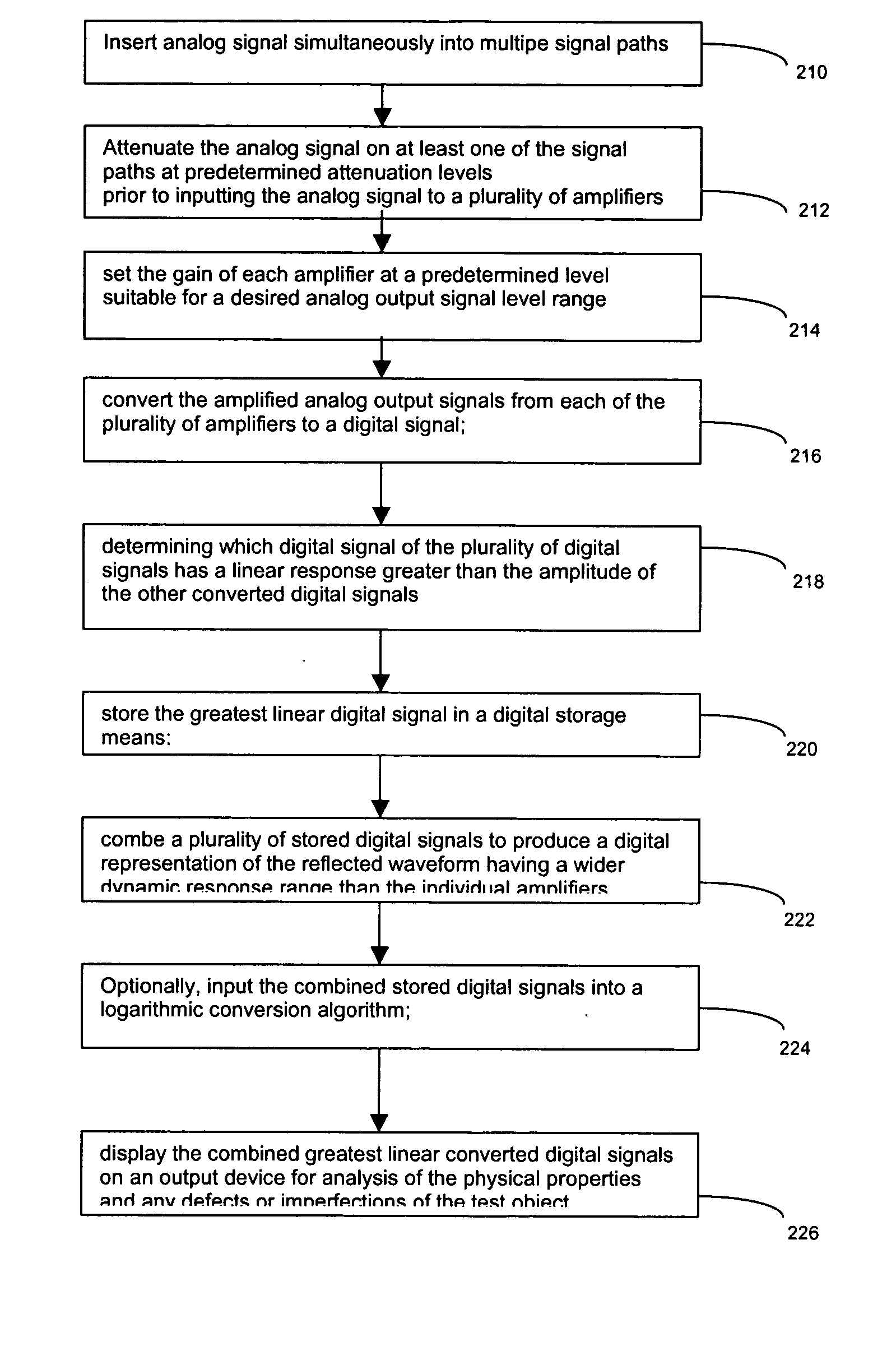
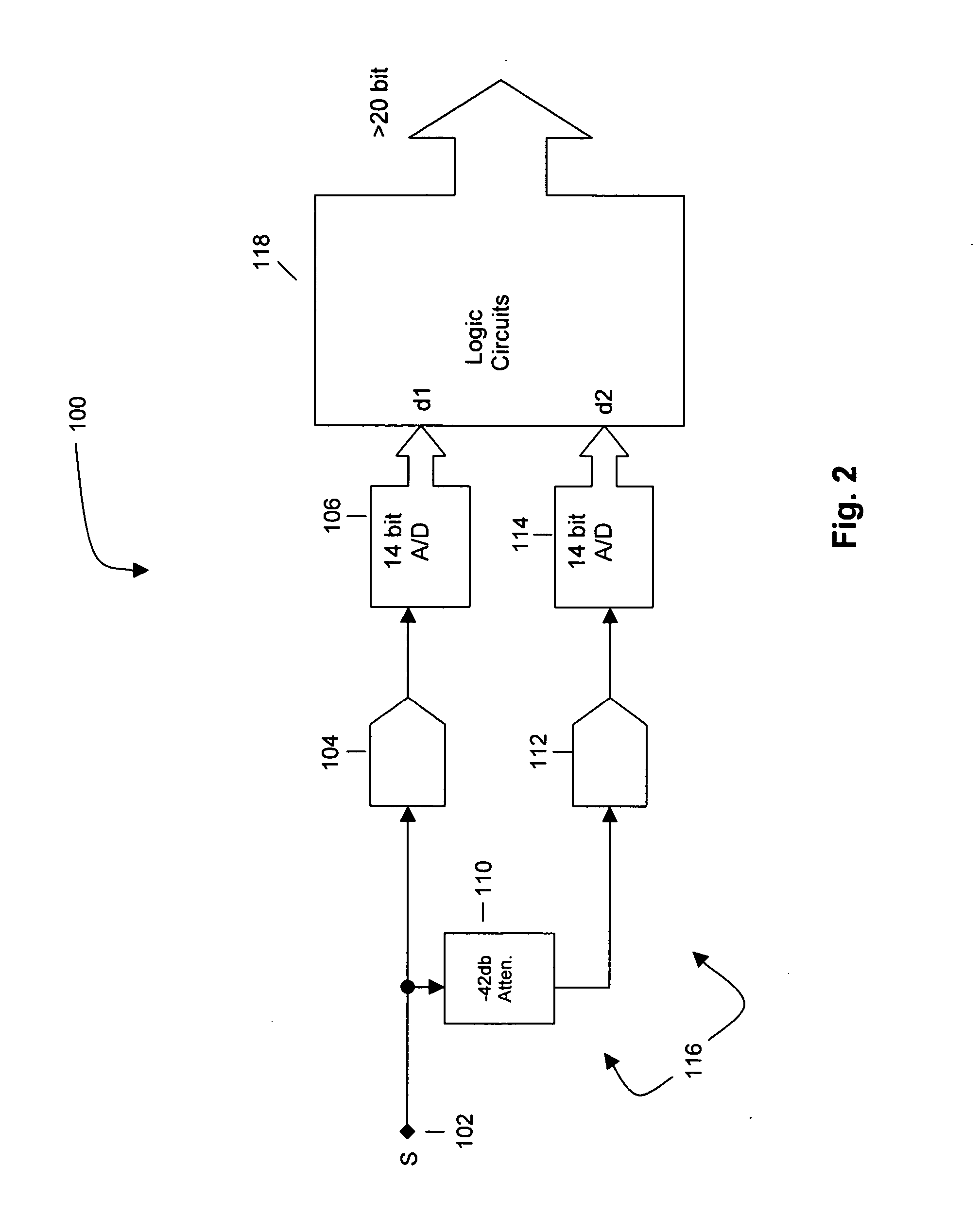
The apparatus and method of the present invention provides a plurality of linear amplifiers simultaneously processing an ultrasonic signal. Each amplifier of the plurality of linear amplifiers has a predetermined gain level suitable for achieving the desired output signal level for input to an analog to digital (A/D) converter for processing. The output of each amplifier is sampled by each respective A/D converter at a very high frequency to convert the analog signal output of each of the linear amplifiers to a digital signal. Logic circuits simultaneously monitor all of the output digital signals from the A/D converters. The logic circuits determine which output of the A/D converters has the greatest linear output and stores the selected output in a memory storage device. The saved output waveforms are subsequently combined into a continuous linear digital output that has a dynamic response range that is approximately the sum of the individual dynamic response ranges of the individual amplifiers and A/D converters. The combined continuous linear digital output waveform may be input to a logarithmic conversion to produce a waveform having a wide dynamic range.

Description

FIELD OF THE INVENTION [0001] The present invention is directed to a method and system for processing acoustic signals for use in ultrasonic inspection and testing, and more particularly to simultaneously processing an acoustic signal with multiple linear amplifiers to obtain a combined linear digital output signal having a dynamic response range that is greater than the individual ranges of the amplifiers. BACKGROUND OF THE INVENTION [0002] Ultrasonic inspection employs high frequency, ultrasonic waves generated by a transducer to examine test objects and make measurements. Ultrasonic inspection can be used for detection of flaws in test objects, and for performing evaluation, dimensional measurements, material characterization, and more on objects. Measurement procedures initially developed for metals have been extended to engineered materials such as composites, where such characteristics as anisotropy and inhomogeneity are of concern. Advances in digitization and computing capab...

Claims


Application Information

Patent Timeline
Patent Type & Authority Applications(United States)
IPC IPC(8): G01N29/00
CPCG01N29/36G01N29/44G01N2291/02854H03M1/1235G01N29/04H03F1/32H03M1/12
Inventor CUFFE, JOHN MICHAELBUSCH, KLAUS-PETERHERBSTER, SCOTT ALLEN
Owner GE INSPECTION TECH LP
Why Eureka
Try Eureka