
Separation Type Multiphase Flow Meter Apparatus

a flow meter and multi-phase technology, applied in the direction of volume metering, instruments, specific gravity measurement, etc., can solve the problems of unsuitable configuration and unsuitable subsea use, and achieve accurate flow rate values, low energy, and high signal attenuation

Active Publication Date: 2020-07-02
FMC KONGSBERG SUS
View PDF0 Cites 0 Cited by
  • Summary
  • Abstract
  • Description
  • Claims
  • Application Information

AI Technical Summary

Benefits of technology

The present invention provides a multiphase meter apparatus that can handle a wide range of gas-liquid separations and is designed for use in high salinity water. The apparatus allows for accurate flow rate measurements and potential for more accurate measurement of liquid properties using a small-diameter multiphase meter. Additionally, the apparatus allows for scaling of the flow through increasing the diameter of the dual-phase meter, which can provide accurate flow rate values for the sub-stream in the first measuring conduit. This invention is useful in situations where there is limited or no gas-liquid separation, e.g. when slugs occur in the system.

Problems solved by technology

However, this configuration is not suited for subsea use.
This, in turn, requires an active regulation of the separation module, which normally is not an option in subsea applications.
Also, the configuration is not suitable when there are slugs in the hydrocarbon flow, as is common in subsea applications, since the required GVF operational range required by conventional multi-phase and wetgas meters cannot be guaranteed under such circumstances.

Method used


Image

  • Separation Type Multiphase Flow Meter Apparatus
  • Separation Type Multiphase Flow Meter Apparatus

Examples


Embodiment Construction

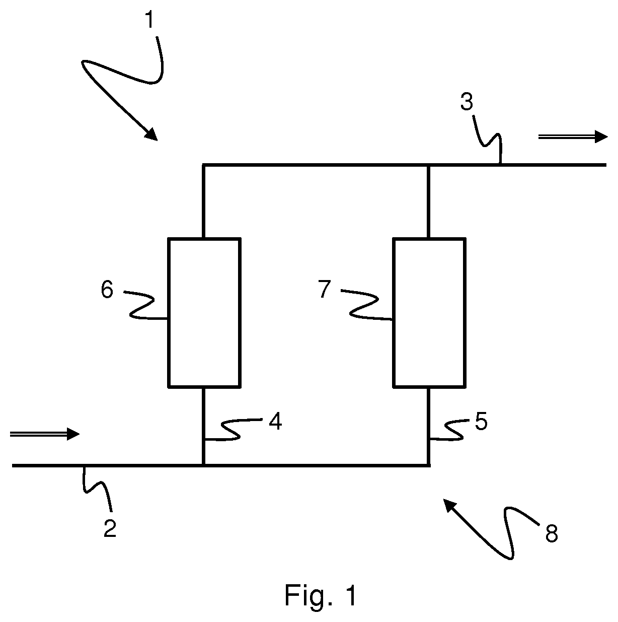
[0036]FIG. 1 shows an embodiment of a separation type multiphase flow meter apparatus 1 according to the invention.

[0037]The apparatus 1 comprises an inlet conduit 2 and an outlet conduit 3. The apparatus 1 further comprises first and second measuring or separation conduits 4, 5 being arranged side by side between and in fluid communication with the inlet and outlet conduits 2, 3, thus allowing parallel fluid flows therein. Consequently, the first measuring conduit 4 forms a first conduit path of the apparatus 1 and the second measuring conduit 5 forms a second conduit path of the apparatus 1, which first and second conduit paths run side by side in a parallel, i.e. non-serial, configuration.

[0038]In operation, a multiphase fluid will enter the apparatus 1 via inlet conduit 2 and be split into two sub-streams in measuring conduits 4 and 5, which sub-streams will be re-joined in outlet conduit 3 and exit the apparatus 1 via this conduit, as is indicated by the arrows in FIG. 1. Condu...


PUM

PropertyMeasurementUnit
diameteraaaaaaaaaa
flow rateaaaaaaaaaa
phaseaaaaaaaaaa

Abstract

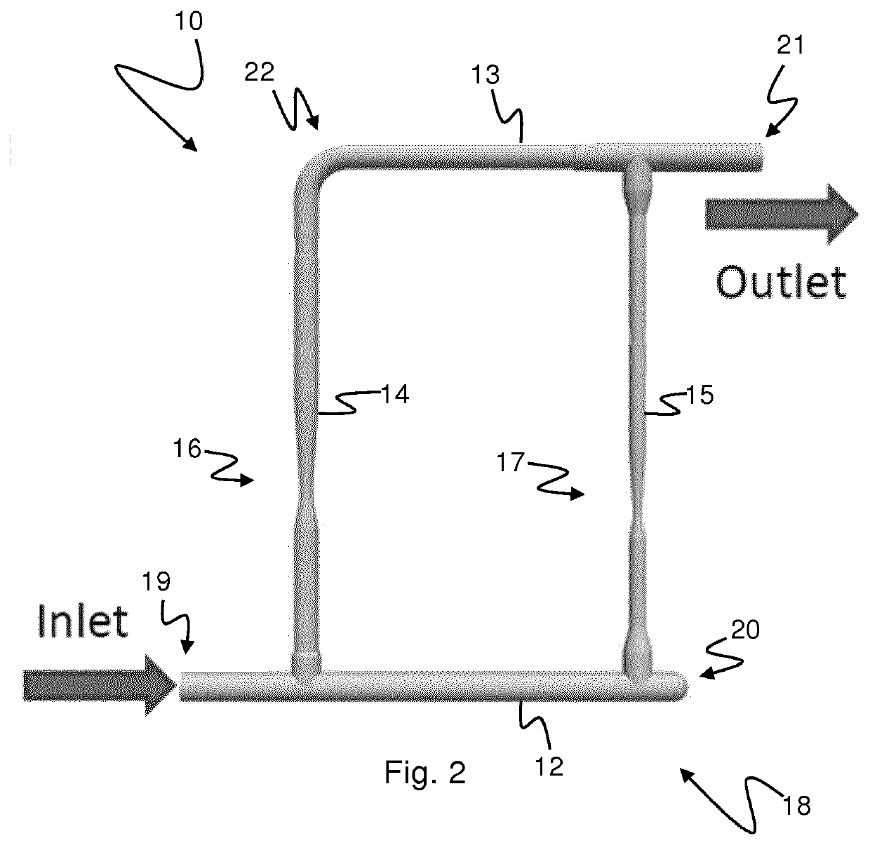
A separation type multiphase flow meter apparatus (10) comprising a separation module (18) arranged to at least partially separate a multiphase stream comprising water, hydrocarbon liquid and hydrocarbon gas into a first sub-stream comprising a gas fraction and a second sub-stream comprising a liquid fraction. The apparatus comprises a first metering device (16) for measuring the flow rate of the first sub-stream, and a second metering device (17) for measuring the phase fraction and the flow rate of the second sub-stream, wherein the second metering device is arranged to measure the water-in-liquid ratio (WLR) of the second sub-stream, wherein the apparatus is arranged to use the WLR measured by the second metering device as a measure also for the WLR of the first sub-stream, and wherein the cross-sectional flow area of the first metering device is larger than the cross-sectional flow area of the second metering device.

Description

FIELD OF THE INVENTION[0001]The present invention relates to a separation type multiphase flow meter apparatus comprising a separation module arranged to at least partially separate a multiphase stream comprising water, hydrocarbon liquid and hydrocarbon gas into a first sub-stream comprising a gas fraction and a second sub-stream comprising a liquid fraction.BACKGROUND[0002]The present invention relates to a hydrocarbon multiphase flow meter (MPFM), i.e. an apparatus for measuring the individual flow rates of hydrocarbon liquid, water and hydrocarbon gas in a multiphase hydrocarbon flow. In particular, the present invention relates to a separation type MPFM.[0003]In this specification the terms “oil” and “gas” will be used to denote hydrocarbons which are in the liquid and gaseous state, respectively, at the prevailing temperature and pressure conditions, and the term “phase” will be used to denote one constituent of gas, oil and water in a mixture of any number of the three.[0004]...

Claims


Application Information

Patent Timeline
Patent Type & Authority Applications(United States)
IPC IPC(8): G01F7/00G01N33/28G01F15/08G01F1/74G01F1/66G01N22/04
CPCG01N22/04G01F7/00G01N33/2847G01F15/08G01F1/662G01F1/74G01N33/2823G01F1/34G01N9/24G01F5/00
Inventor GUNDERSEN, KENNETH
Owner FMC KONGSBERG SUS
Learn More