Patio heater with directional control

a directional control and heater technology, applied in the field of outdoor heating methods and equipment, can solve the problems of not being safe for children, not being efficient enough to be placed on the periphery of the seating area, and affecting the safety of children, so as to improve the economical use and distance and direction, extend and focus the heat, and increase the distance capability

Inactive Publication Date: 2007-05-10
SUNJOY INDS
View PDF5 Cites 22 Cited by
  • Summary
  • Abstract
  • Description
  • Claims
  • Application Information

AI Technical Summary

Benefits of technology

The present invention provides a patio heater that is more efficient and flexible in its heat projection. The heat reflector can be angled to redirect heated gases and air in a desired direction, with increased distance capability. This improves the efficiency of the heater and allows it to reach a wider area. The heater can also be used in a traditional 360 degree heating mode and can still deliver maximum efficiency.

Problems solved by technology

The technical problem addressed in this patent is the limitations of current free-standing heaters which require placement at the center of the area to be heated and often result in wasted energy and fuel due to their design. There is a need for a portable heater that can safely project heat both radially and in a chosen direction based on the user's requirements.

Method used


Image

  • Patio heater with directional control
  • Patio heater with directional control
  • Patio heater with directional control

Examples


Embodiment Construction

—PREFERRED EMBODIMENT

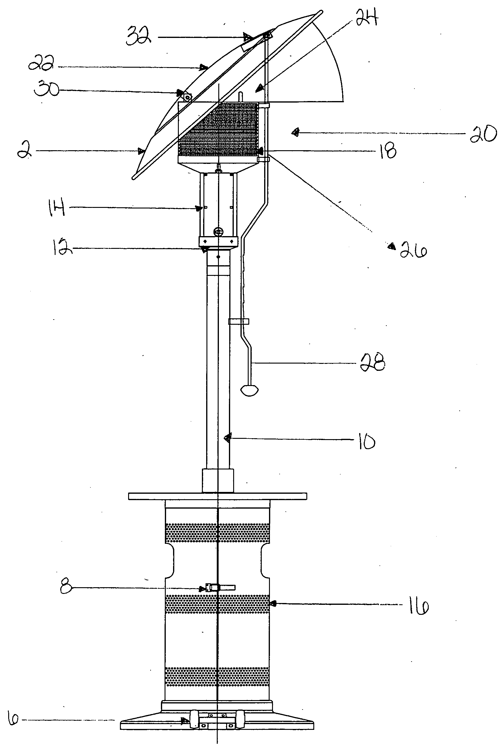
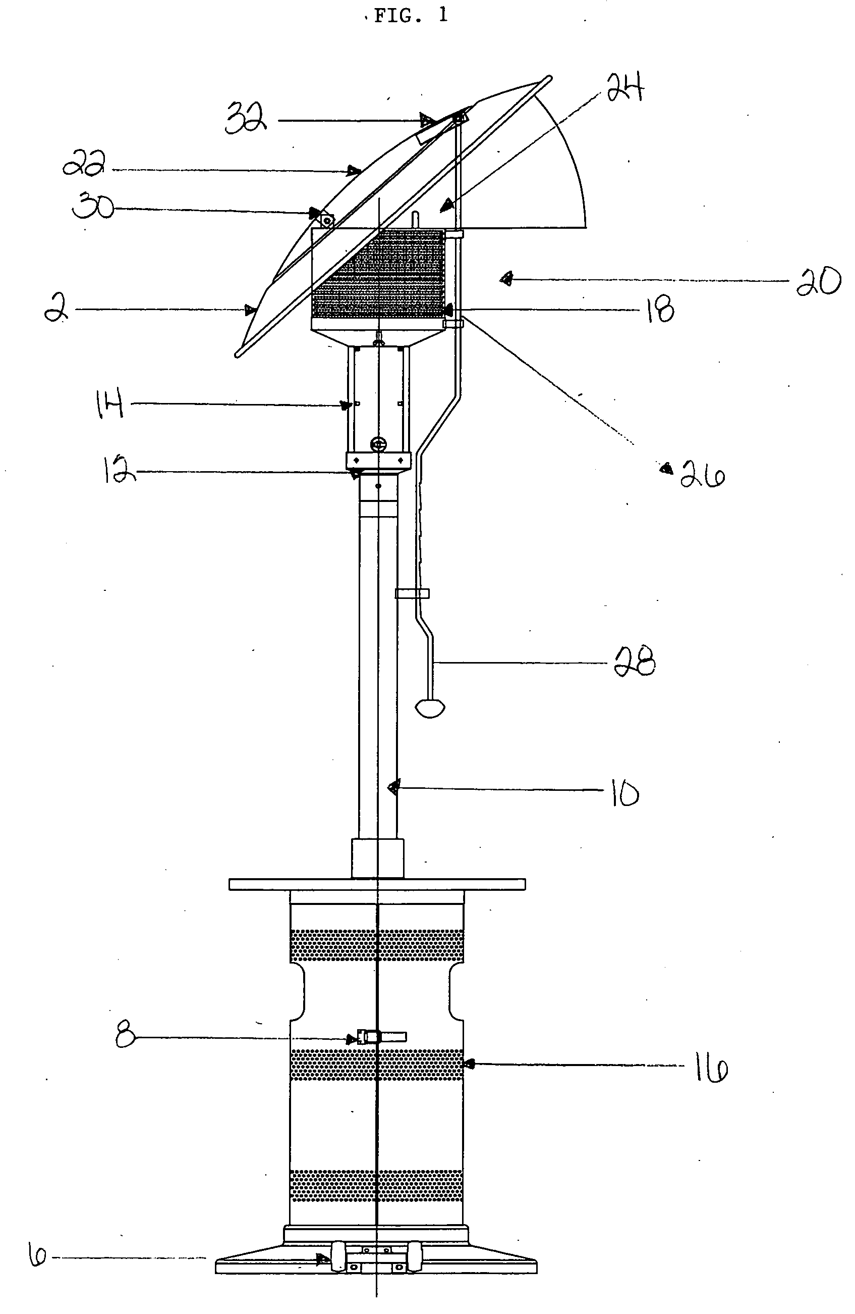
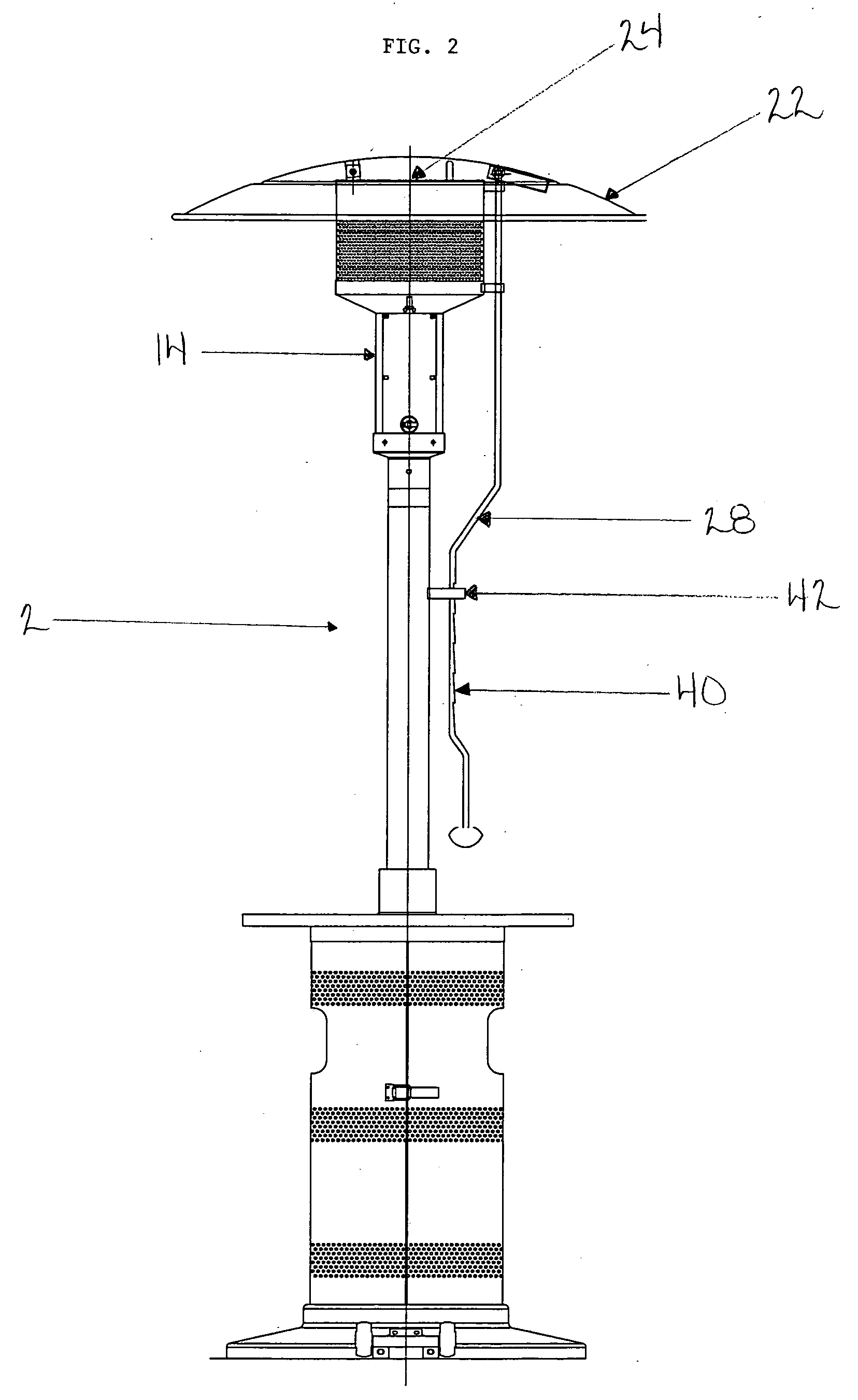
[0017] Referring now to the drawings, FIG. 1 shows a first embodiment of the patio heater 2 of the instant invention, comprising an elongated support member 10 with an upper end 12. The upper end 12 supports the heat source 14, which heat can be generated by combustion, resistance or some other means as the circumstance or need may require.

[0018] In a first embodiment, fuel such as LP gas or propane is stored in the enclosure 16 at the base of the elongated support member 10. The elongated support member 10 is preferably hollow in order to permit the fuel to safely travel from the enclosure 16 to the heat source 14, where combustion or other heat generation activity can occur. The shown embodiment also contains a clasp 8 that can be opened to access the LP gas or propane. Further, a set of wheels 6 are included for ease of movement and increased flexibility in floor-planning.

[0019] Once heat is generated in the heat source 14, it is directed upward by the side...


PUM


Abstract

The present invention provides a patio heater that has the capability of heating an area in a desired direction rather than heating all areas in all directions radially from the patio heater. The disclosed patio heater has a heat source that sits upon an elongated support member that spaces the heat source vertically away from ground level to protect the user from accidentally coming too close to the heat source. The heat source is enclosed in a receptacle having one or a plurality of side walls that extend above the heat source to form a heat exhaust opening directed generally upward. The heat generated by the heat source is reflected in a desired direction by a heat reflector located above the heat exhaust opening and supportively connected to the receptacle. A directional control mechanism is provided for angling the heat reflector relative to the heat exhaust opening and, thus, reflecting the heat in the desired direction.

Description


Claims


Application Information

Patent Timeline
Owner SUNJOY INDS
Why Eureka
Try Eureka