RFID system, RFID cable system, and RFID cable laying method

a technology of rfid and cable system, which is applied in the direction of electrical signalling details, mechanical actuation of burglar alarms, instruments, etc., can solve the problems of increasing the cost, the function of the reader in the terminal block, and the failure of the write type reid, so as to eliminate human errors and realize efficient work

Active Publication Date: 2007-05-10
HITACHI LTD
View PDF10 Cites 35 Cited by
  • Summary
  • Abstract
  • Description
  • Claims
  • Application Information

AI Technical Summary

Benefits of technology

[0015] According to the present invention, an REID system capable of eliminating human errors and ensuring efficient work can be realized.

Problems solved by technology

(1) The write type REID tends to cause a failure and is troublesome due to the necessity of rewrite each time the situation is changed.
(2) The incorporation of the reader function in the terminal block increases the cost.
(3) The known techniques are targeted for only the connecting operation and are not adapted for the sequence test that takes the most expense in time and effort.

Method used


Image

  • RFID system, RFID cable system, and RFID cable laying method
  • RFID system, RFID cable system, and RFID cable laying method
  • RFID system, RFID cable system, and RFID cable laying method

Examples


Embodiment Construction

[0036] One embodiment of the present invention will be described below with reference to the drawings.

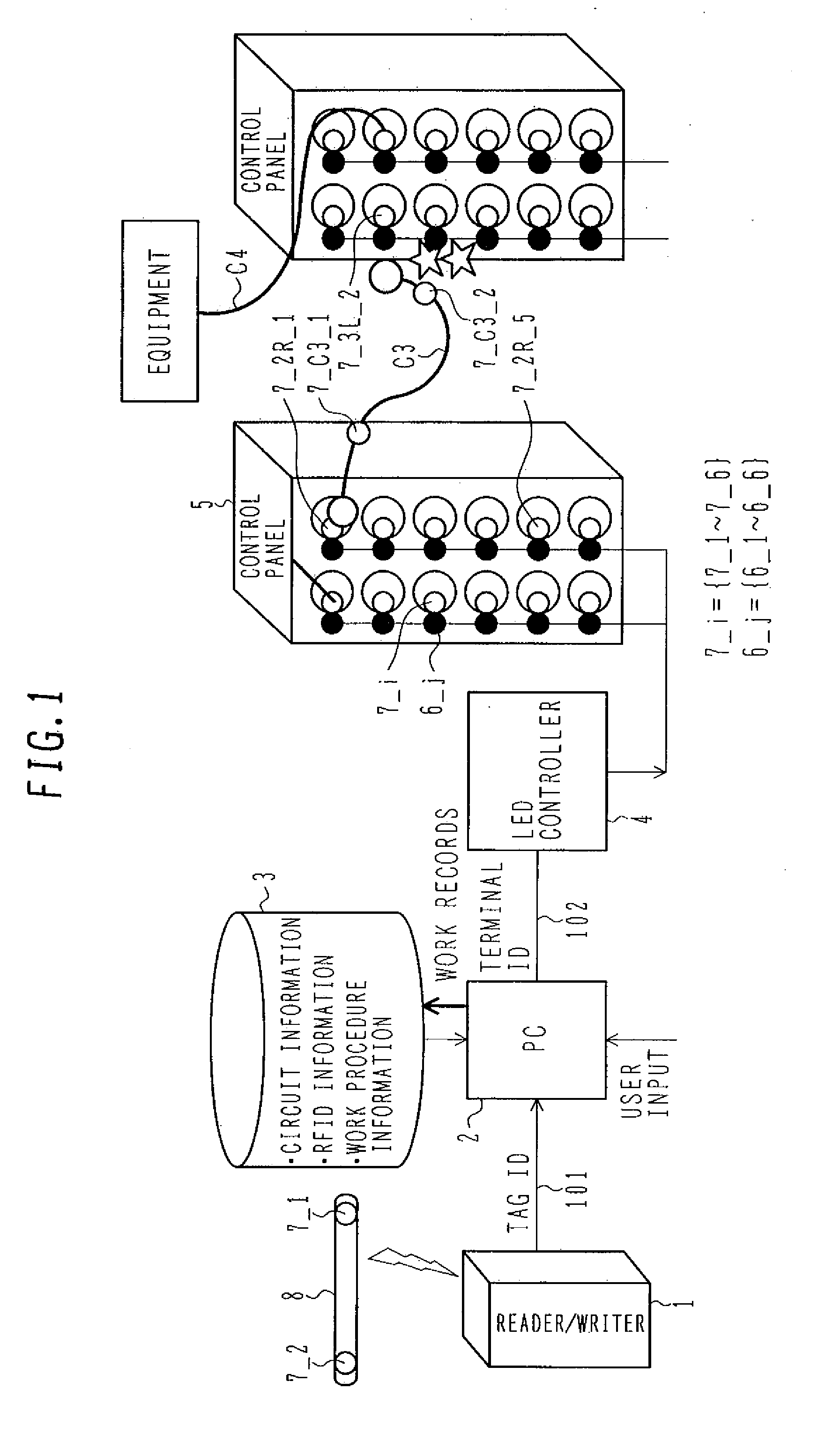
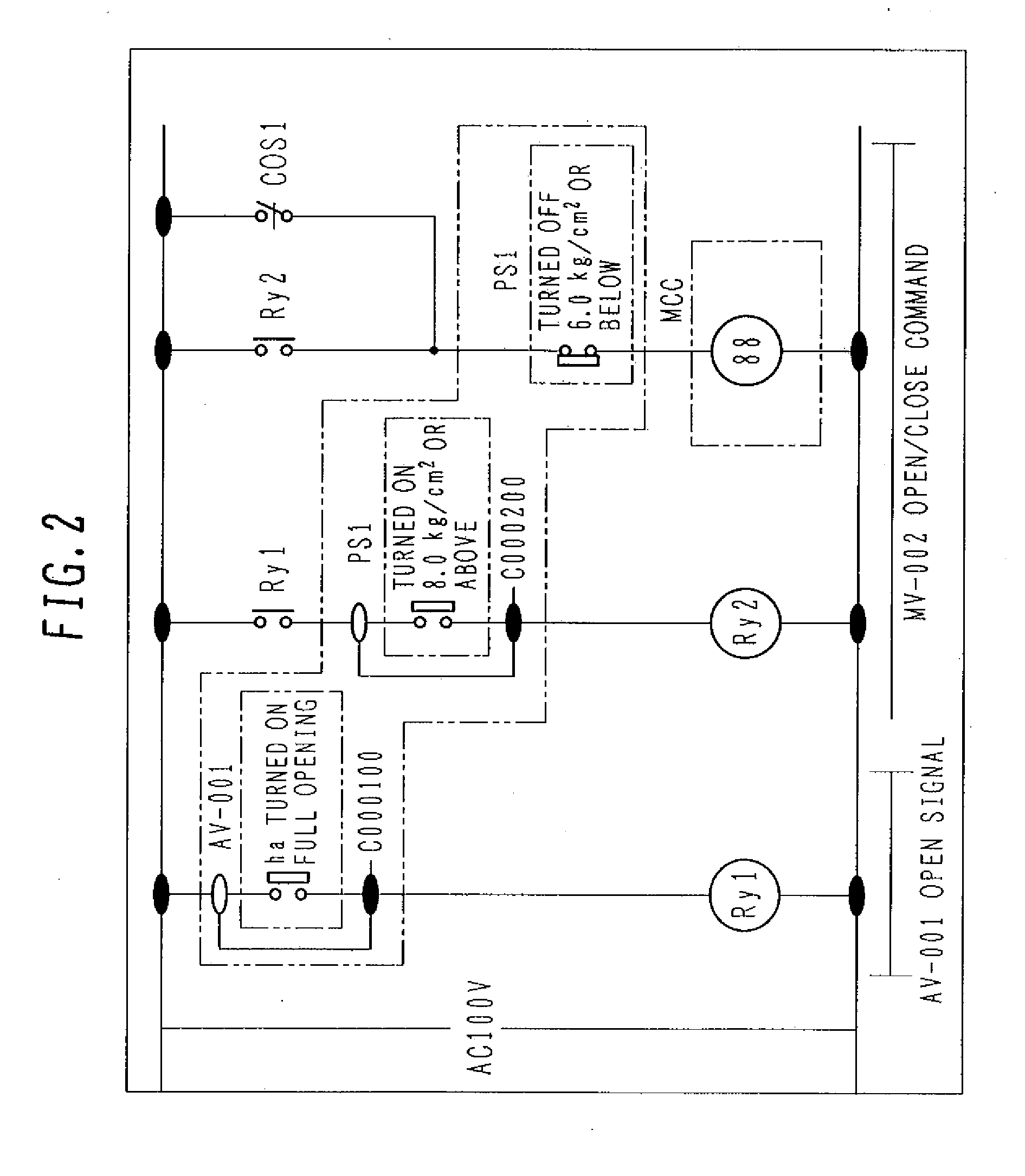
[0037]FIG. 1 illustrates one example of overall configuration of a cable laying system according to one embodiment of the present invention, and practical examples of information held in a data storage 3 are shown in FIGS. 2-5. Examples of operation of a PC 2 are shown in FIGS. 6-16.

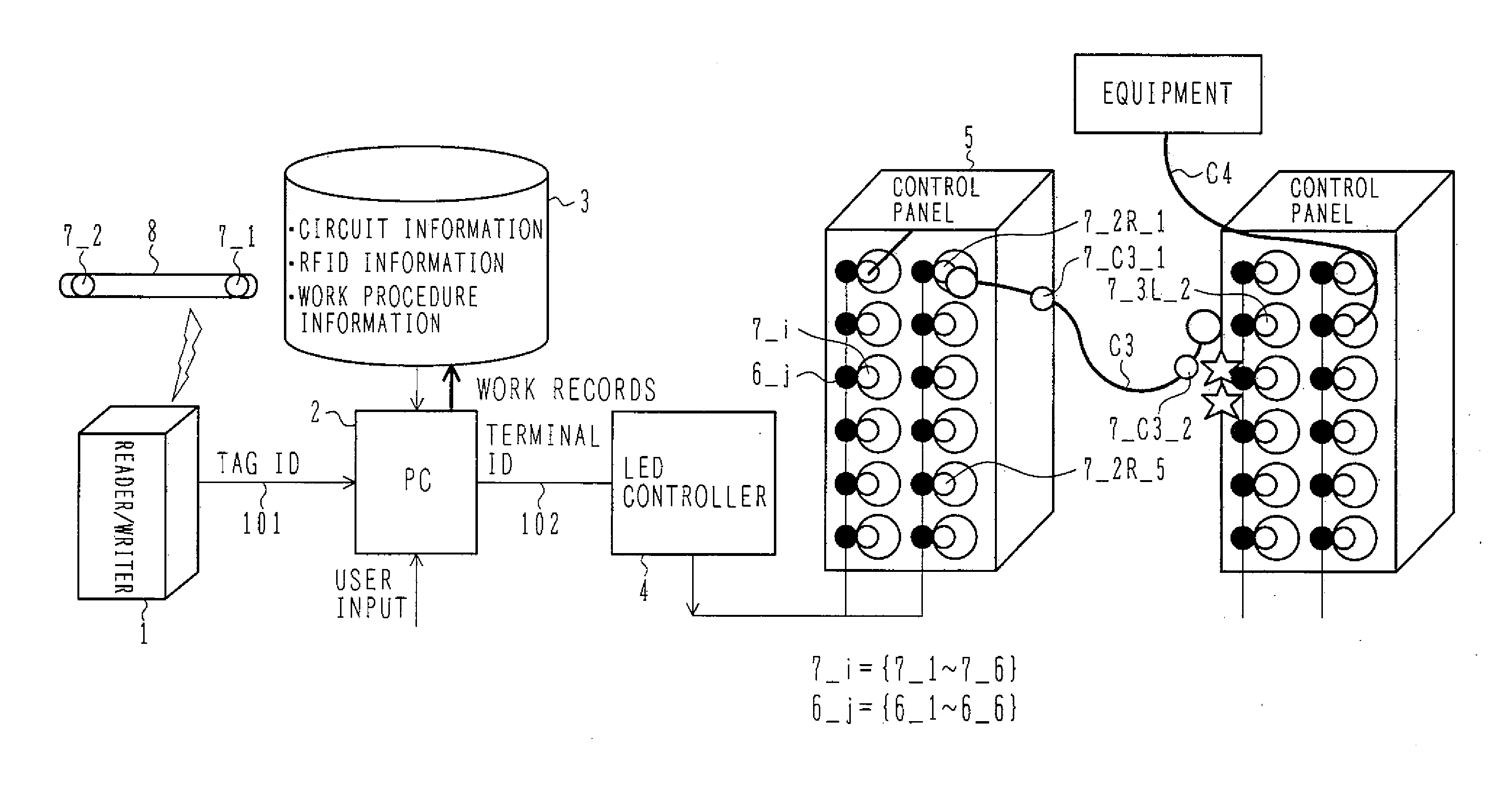
[0038] A cable 8 in FIG. 1 is a cable connecting two terminals as indicated by a cable C3. One end of the cable is connected to a particular terminal of a control board 5. A reader 1 is an RFID reader which reads an ID stored for identification in an RFID (tag) and outputs the read ID (tag ID) to a signal line 101. The reader 1 repeats the read operation at intervals of a predetermined time or reads the tag ID at the timing when a trigger is applied from the PC 2 via a signal line 101. The PC 2 is constituted by any of a personal computer (PC), a personal digital assistant (PDA) or a small-sized microc...


PUM


Abstract

When an RFID is attached to an object to assist testing operations, the following problems are encountered; (1) the RFID of write type tends to cause a failure and is troublesome due to the necessity of rewrite each time the situation is changed, (2) the incorporation of the reader function in a terminal block increases the cost, and (3) the known techniques are targeted for only the connecting operation and are not adapted for a sequence test that takes the most expense in time and effort. The operations are aided by using an RFID reader and a terminal having the function for accessing a database of circuit information, RFID information, and test procedure information.

Description

BACKGROUND OF THE INVENTION [0001] 1. Field of the Invention [0002] The present invention relates to an RFID (Radio Frequency Identification) system. [0003] 2. Description of the Related Art [0004] When electric cables are laid in plants, railways and buildings, work specifications are prepared from design circuit diagrams. While referring to the work specifications, workers perform laying, connecting, testing and removing operations. The operations are progressed as follows. First, the workers lay cables in a plant, for example, while referring to work instructions indicating the start point and the end point of each cable. FIG. 2 illustrates sequence information printed on paper and shows a sequence for a part of the entire plant. FIG. 3 illustrates information complementing the sequence information in FIG. 2 and shows a connection diagram of terminal blocks and cable wires which is printed on paper. The connecting and disconnecting operations are carried out while referring to FI...

Claims


Application Information

Patent Timeline
Patent Type & Authority Applications(United States)
IPC IPC(8): G06F17/00G08B13/14
CPCG06Q50/04Y02P90/30
Inventor YOKOTA, TOSHIMIARAKI, KENJIUTAKA, KENJIMATSUMOTO, NORITAKATAKADA, MASATOSHISHIGEMI, RYOSUKEOTA, CHIKARA
Owner HITACHI LTD
Why Eureka
Try Eureka