Device for detecting non-metallic objects located on a human subject

a technology for detecting non-metallic objects and human subjects, applied in the direction of geological detection using milimeter waves, using reradiation, instruments, etc., can solve the problems of no sophisticated measuring instruments and extremely quick completion of measurement, and achieve the effect of simple design

Inactive Publication Date: 2007-05-10
THALES SA
View PDF15 Cites 38 Cited by
  • Summary
  • Abstract
  • Description
  • Claims
  • Application Information

AI Technical Summary

Benefits of technology

[0011] This technique is simple to design, inexpensive, does not require any great computing power and is very well suited t

Problems solved by technology

The complete measurement is extremely quick and

Method used


Image

  • Device for detecting non-metallic objects located on a human subject
  • Device for detecting non-metallic objects located on a human subject
  • Device for detecting non-metallic objects located on a human subject

Examples


first embodiment

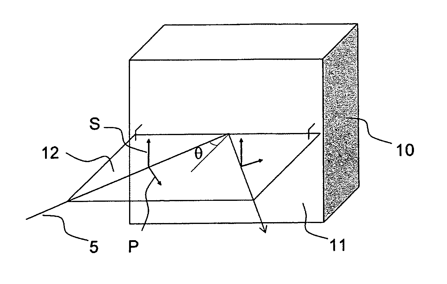
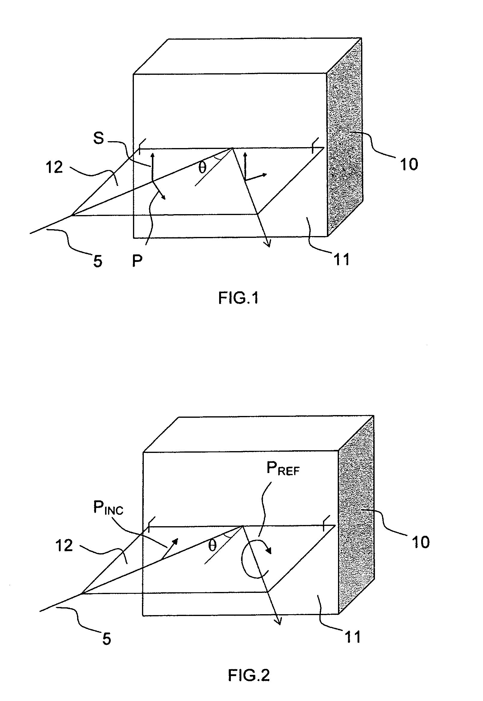
[0073] The first means 41 of measuring the polarimetric characteristics of the reflected signal are of different types. When the polarization sent is kept constant, the means 41 are of ellipsometric type, namely that, they allow the main orientation and ellipticity of the received polarization to be measured. There are then various possible techniques for carrying out this measurement. In a first embodiment, the analysis system is said to be “with rotating analyzer”. It is formed by a rotating polarizer placed in front of an intensity detector and means of rotating said polarizer. For example, a microwave horn connected to a microwave guide constitutes a good polarizer, this guide is then connected to a rotating joint providing the swiveling link between the guide and the coaxial connector linked to the intensity detector. The guide and the horn are driven rotation-wise by a direct current motor and the absolute angular position of the horn is measured by an incremental encoder. The...

second embodiment

[0074] The rotating analyzer solution has the advantage of being simple to implement at low cost, but this method has the drawback of involving moving parts. In a second embodiment, the complex amplitude of two orthogonal polarizations that make up the polarization to be analyzed is measured. For this, a so-called orthomode horn is used which gives, on two separate channels, the two vertical and horizontal incident polarizations. Having these two signals, on the one hand each amplitude and then the relative phase shift between these two amplitudes are measured. The measurement can then be done at a repeat frequency measured in kilohertz.

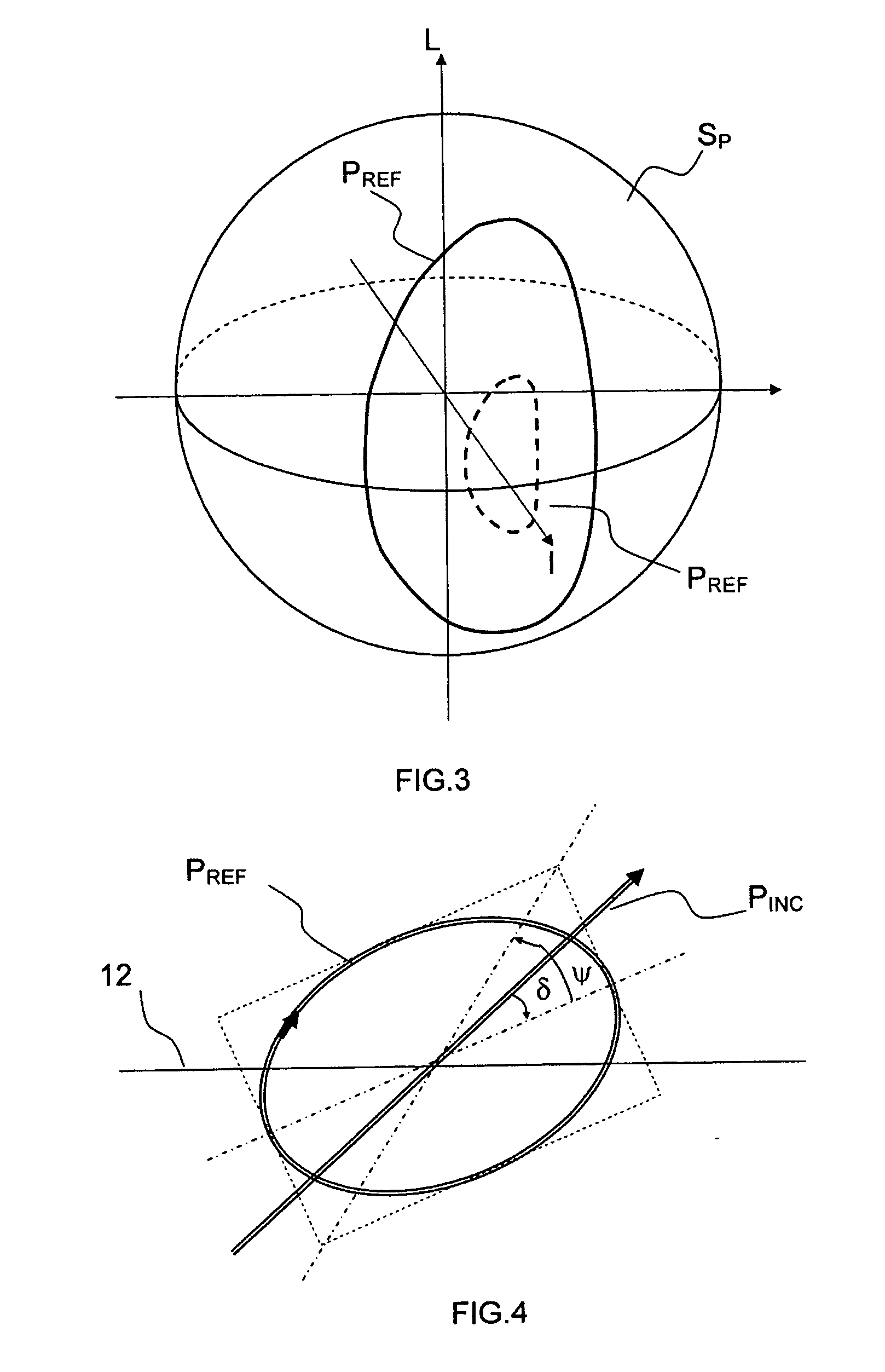
[0075] When the polarization sent varies over time, for example when the source or the sending horn comprises means for sending different combinations of parallel and perpendicular polarizations varying over time, then the receiving horn is preferably a horn that can receive a polarization oriented at 45° from the reflection plane. By analyzing the v...


PUM


Abstract

The field of the invention is that of devices for detecting objects concealed on human subjects. These devices are more particularly dedicated to the surveillance and protection of airport areas and transport airplanes. Currently, the devices rely either on X-ray detection or on microwave imaging. In the former case, the system can prove hazardous to human beings, and in the other case, the device raises ethical problems. The invention proposes a device whose operation relies on the reflective properties of the microwave signals polarized by the suspect objects that we are seeking to detect. This device can be portable or installed on security gates. This technique is simple to design, inexpensive, does not require any great computing power and is very well suited to the objects to be detected. The complete measurement is extremely quick and requires no sophisticated measuring instrument.

Description

CROSS-REFERENCE TO RELATED APPLICATIONS [0001] The present Application is based on International Application No. PCT / EP2004 / 053328, filed on Dec. 8, 2004, which in turn corresponds to FR 03 / 15033 filed on Dec. 19, 2003, and priority is hereby claimed under 35 USC §119 based on these applications. Each of these applications are hereby incorporated by reference in their entirety into the present application.BACKGROUND OF THE INVENTION [0002] 1. Field of the Invention [0003] The field of the invention is that of devices for detecting objects concealed on human subjects. These devices are more particularly dedicated to the surveillance and protection of airport areas and transport airplanes, but they can also be positioned at the entrance of protected buildings, controlled access areas or other transport means (ships, trains, etc.) for which access is to be secured. [0004] 2. Description of the Prior Art [0005] To ensure the safety of the passengers in the airplanes, cargo hold luggage ...

Claims


Application Information

Patent Timeline
IPC IPC(8): H01J40/14G01S7/02G01S7/41G01S13/04G01V8/00
CPCG01S7/024G01S7/414G01S13/04G01S13/887G01V8/005
Inventor RICHARD, MATTHIEULEHUREAU, JEAN-CLAUDECACHIER, GERARD
Owner THALES SA
Why Eureka
Try Eureka