Monitoring system

Inactive Publication Date: 2007-05-10
ALLIED HEALTHCARE PROD INC
View PDF19 Cites 2 Cited by
  • Summary
  • Abstract
  • Description
  • Claims
  • Application Information

AI Technical Summary

Benefits of technology

[0018] Each panel is a single entity device or unit providing an assembly of grouped modular configuration for monitoring gas source lines for multiple parameters, such as pressure, temperature, etc. The panels can be located throughout a healthcare or laboratory or clinic or other facility with capability for communication with a central facility having a personal-type computer (PC). Specific modules for each panel may have interrelated functions, providing capability for monitoring gas pressures or vacuum lines, and signaling in response to changes in such pressures or relative pressures. A plurality of different gas variables or lines, and switch inputs, can be monitored for signaling and/or alarm purposes, thereby avoiding the need for burdensome multiplication of sensors and alarms as additional variables or lines which might later require monitoring after installation of the monitoring system. The monitoring system is thus readily expandable whether at the panel locations or in the overall sense.
[0019] Because the monitoring system may vary in size according to the facility in which it is installed, e.g., whether it be a hospital complex, or a small clinic, the monitoring system is designed and constructed according to a modular design philosophy in order to allow monitoring modules, including PCBs and components thereof, to be selectively configured and then selected for different uses in the monitoring system. In that way the monitoring system facilitates flexible growth. In the monitoring system PCB design is shared by different modules, and identical PCBs can be readily configured with different circuit elements according to the purpose required of the PCB for constructing a specific module. Thus, for the first time, a monitoring system achieves a universality or interchangeability of circuit d

Problems solved by technology

As a specific example, breathing oxygen pressure at a predetermined location may need to be sensed because, if breathing oxygen is too high or too low, patient safety may be compromised.
This

Method used


Image

  • Monitoring system
  • Monitoring system
  • Monitoring system

Examples


Embodiment Construction

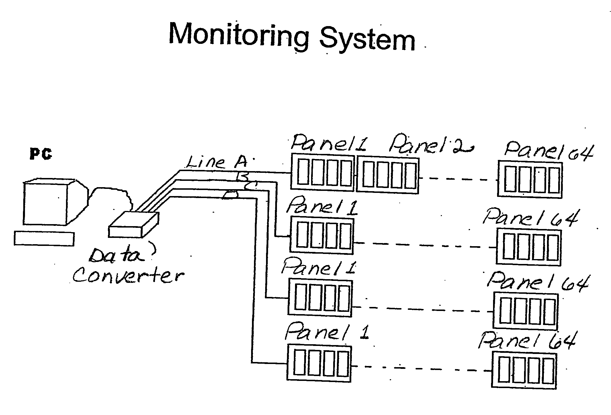
[0033] Referring to the drawings, a monitoring system is illustrated and generally designated as 10 in FIG. 1. In this implementation, the monitoring system 10 may include a computer system 12 which is electronically connected by a data converter 14 to one or more panels 16 such that the data converter 14 provides monitoring data from one or more data lines 18 to computer system 12.

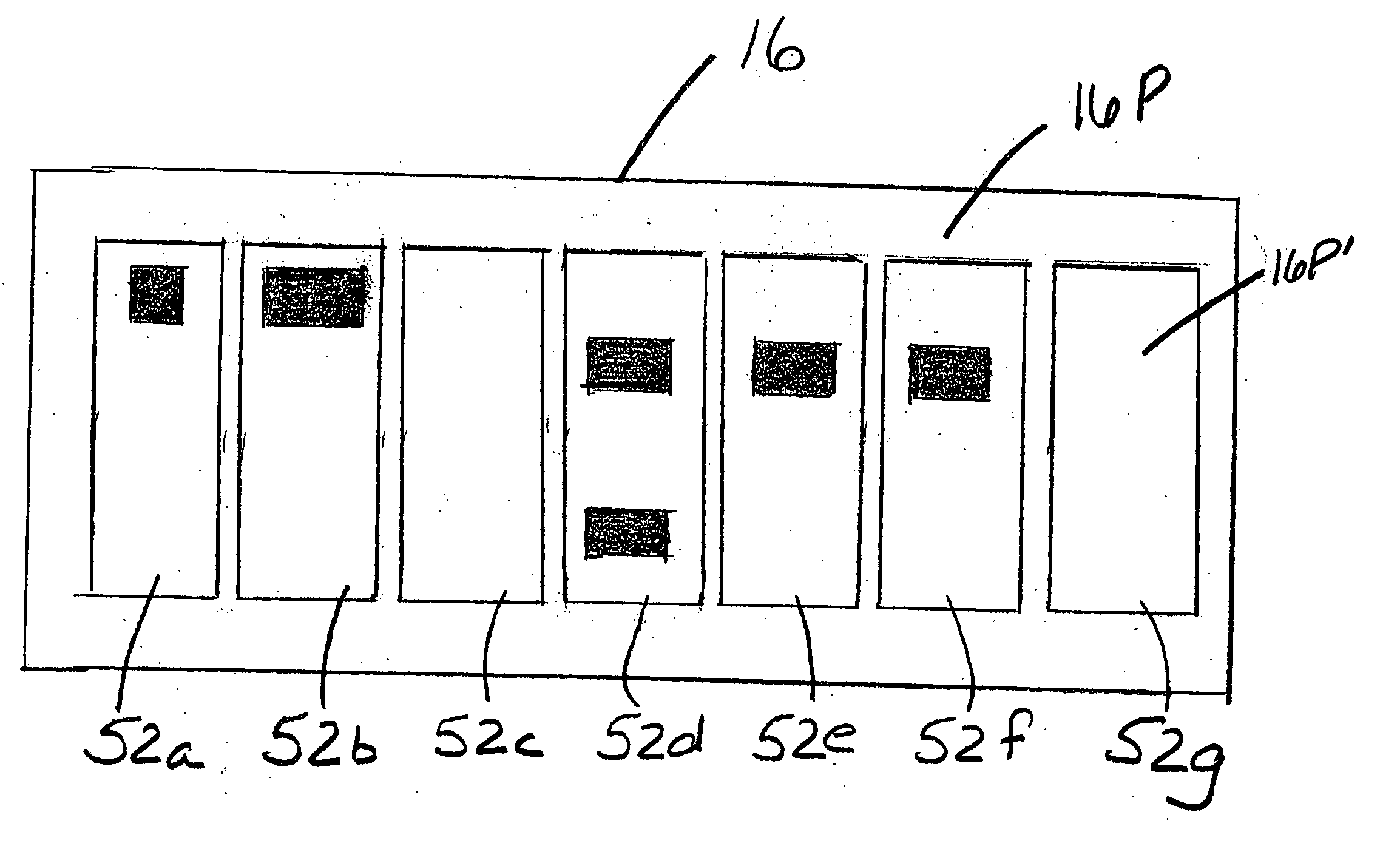
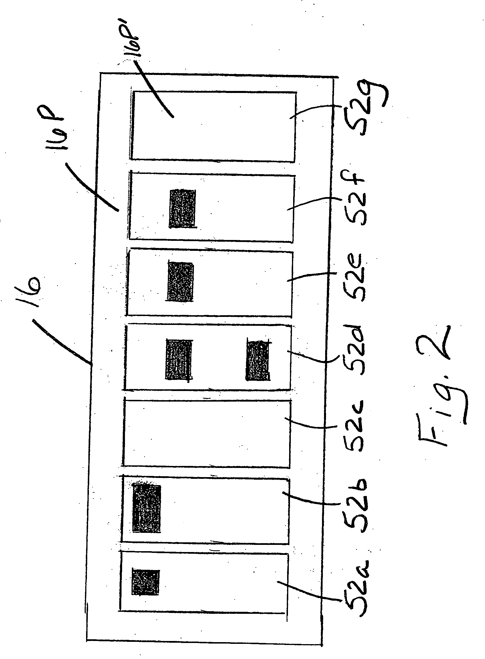
[0034] One or more panels 16 are provided that monitor status of one or more measurable variables. Each panel 16 is a single entity device or unit (as more fully described below) providing an assembly of grouped modular configuration for monitoring gas source lines for multiple parameters, such as pressure, temperature, etc. The panels 16 can be located throughout a healthcare or laboratory or clinic or other facility with capability for communication with computer system 12 which may be a PC including the usual keyboard and printer or printers and other accessories, all as being part of the usual periph...


PUM


Abstract

A monitoring system to enable a facility to monitor variables for out-of-limit conditions and to signal in response to such an out-of-limit condition, including one or more monitoring panels or so-called alarm panels located for sensing one or more variables at one or more given location within a facility such as a hospital or laboratory to sense and respond to data associated with out-of-limit condition. The one or more panels recognize the existence of an out-of-limit condition so as to determine the nature of the out-of-limit condition, such as underpressure or overpressure, and provide the information regarding such condition so as to enable such a condition to be remedied. One or more panels are selectively provided with one or more circuit modules which can be selectively configured for sensing different conditions in the facility, and the modules provide an assembly of grouped modular configuration with each module monitoring multiple possible variables.

Description

BACKGROUND AND SUMMARY OF THE INVENTION [0001] The invention relates to systems for monitoring the status of conditions or alarm points or alarm variables in healthcare facilities or institutions and, more particularly, to a monitoring system for use in such facilities or institutions and using monitoring panels of modular character capable of monitoring a plurality of parameters and providing alarms or other communications signifying out-of-limit conditions. [0002] In healthcare and laboratory installations such as hospitals, laboratories, research facilities, clinics and other health-related or scientific or laboratory facilities where there are piped medical gasses, oxygen, clinical vacuum, nitrous oxide, medical air, carbon dioxide, nitrogen, oxygen / carbon dioxide, waste anesthetic gas disposal (WAGD) lines, and various other and also specialty gases, as well as potentially other fluids including gases generally, are provided at various points through such a facility, or where o...

Claims


Application Information

Patent Timeline
IPC IPC(8): G08B19/00
CPCG08B25/14
Inventor KROUPA, KEVIN D.WILSON, JAMES A.SCHOLZ, CHRISTOPHER A.
Owner ALLIED HEALTHCARE PROD INC
Why Eureka
Try Eureka