Cooling apparatus for flat display device

a technology for flat display devices and cooling apparatuses, which is applied in the direction of electric apparatus casings/cabinets/drawers, machines/engines, instruments, etc., can solve the problems of ineffective heat dissipation to the external side, malfunction of flat display devices, and inability to stably operate flat display devices. to achieve the effect of minimizing noise, minimizing noise, and manufacturing with low cos

Inactive Publication Date: 2007-05-10
LG ELECTRONICS INC
View PDF22 Cites 62 Cited by
  • Summary
  • Abstract
  • Description
  • Claims
  • Application Information

AI Technical Summary

Benefits of technology

[0011] An object of the present invention is to provide a cooling apparatus for a flat display device, which is designed to make the flat display device slimmer and effectively dissipate internal heat of the flat display device.
[0017] Still yet another object of the present invention is to provide a cooling apparatus for a flat display device, which can provide high heat dissipation efficiency even for a large-sized flat display device.

Problems solved by technology

However, since a large number of heat-generating components have to be incorporated in a narrow space of the display device, the heat, which is generated by the heat-generating components in the flat display device during the operation of the flat display module, must be effectively dissipated to an external side.
Therefore, if the large amount of heat is not quickly dissipated, the display device may malfunction.
However, although the cooling effect for the specific component can be expected, the heat is not effectively dissipated to the external side.
Therefore, the flat display device cannot be stably operated.
That is, the internal temperature of the flat display device increases to deteriorate the performance of the flat display device.
In this case, although the heat collected in the display device can be effectively discharged to the external side, excessive noise is generated during the operation of the axial fan.
In addition, due to a gap between the axial fan and the flat display module and a thickness of the axial fan, an overall thickness of the flat display device increases.
The holes of the back cover deteriorate strength of the back cover.
In this case, the manufacturing cost increases.

Method used


Image

  • Cooling apparatus for flat display device
  • Cooling apparatus for flat display device
  • Cooling apparatus for flat display device

Examples


first embodiment

[0038] [First Embodiment]

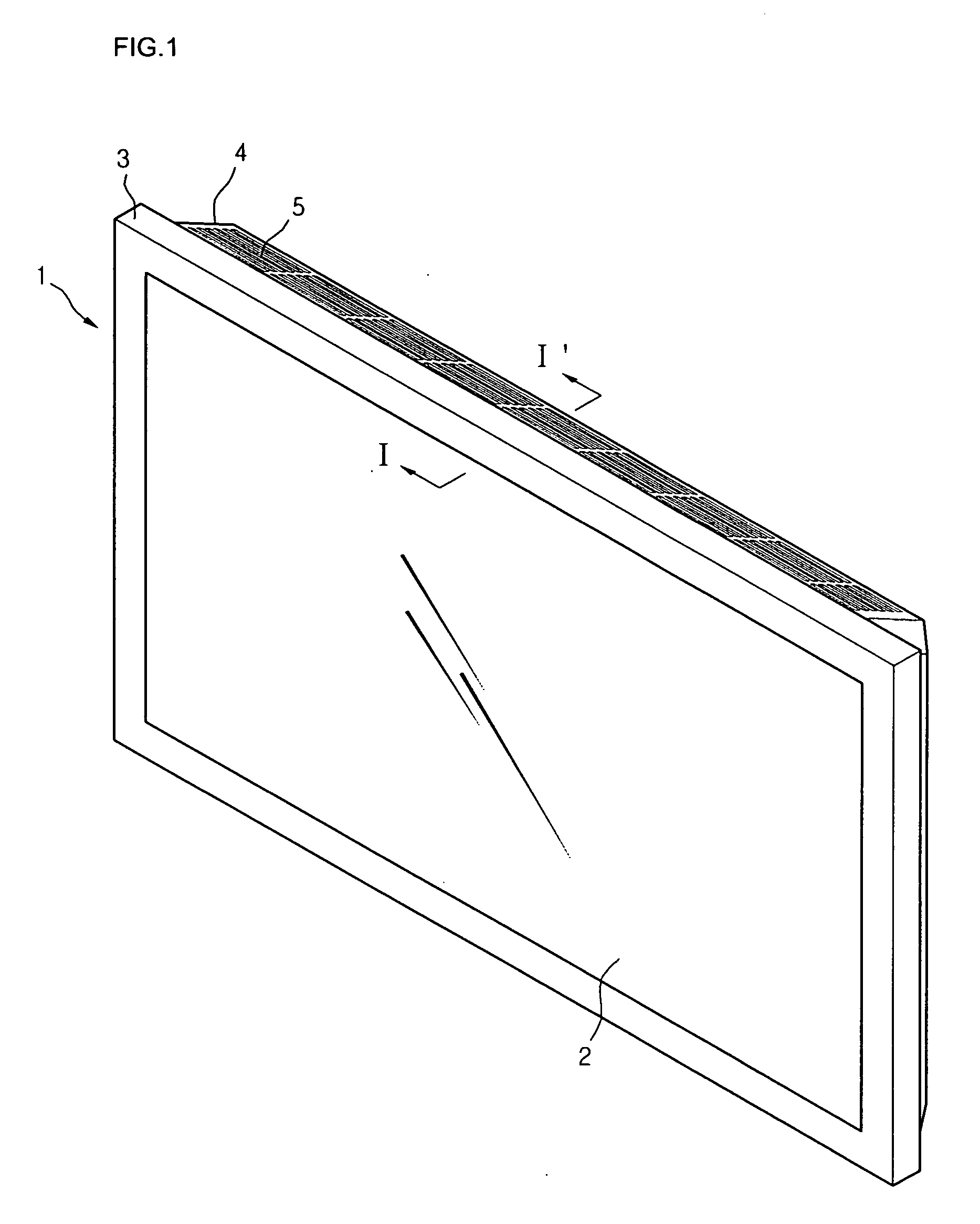
[0039]FIG. 1 is a perspective view of a flat display device according to an embodiment of the present invention.

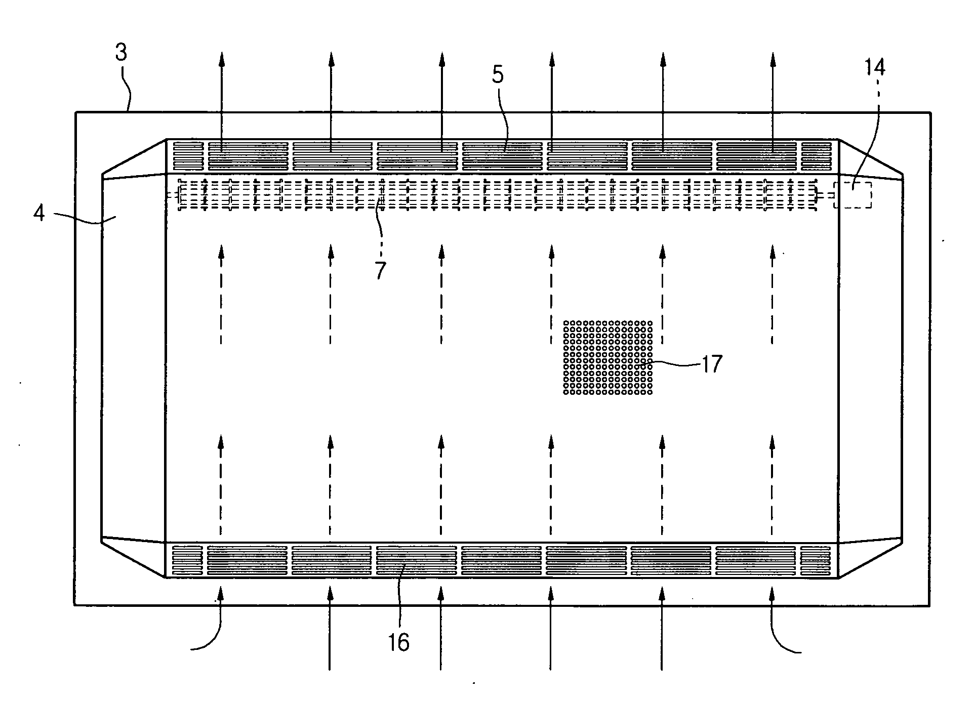
[0040] Referring to FIG. 1, a flat display device 1 of this embodiment includes a flat display module 2, a front cover 3 for supporting and protecting a front portion of the flat display module 2, and a back cover 4 for supporting and protecting a rear portion of the flat display module 2. An air outlet 5 through which internal hot air of the flat display device 1 is exhausted, is formed on an upper peripheral of the back cover 4. The air outlet 5 has a plurality of slits. The slits are arranged not to deteriorate strength of the back cover 4. That is, the air outlet 5 means a portion provided in the back cover 4, of which the inner area has the slits in a type of aggregation.

[0041] The flat display module 2 may be selected from the group consisting of an LCD, an FED, a PDP, and an EL. Preferably, the flat display module 2 may be provided with th...

second embodiment

[0071] [Second Embodiment]

[0072]FIG. 7 is a perspective view of a flat display device according to another embodiment of the present invention. The flat display device of this embodiment is similar to that of FIG. 1. Therefore, only the different portion will be described hereinafter.

[0073] Referring to FIG. 7, a flat display device of this embodiment includes a flat display module 32, a front cover 33 for supporting and protecting a front portion of the flat display module 32, and a back cover 34 for supporting and protecting a rear portion of the flat display module 32. Left and right air outlets 51 and 52 through which internal hot air of the flat display device is exhausted are formed on a top surface of the back cover 34.

[0074] Since the air outlets 51 and 52 are formed on the right and left sides of the top surface of the back cover 34, the cooling efficiency for both sides of the flat display device can be more improved.

[0075]FIG. 8 is a partly broken perspective view of t...

third embodiment

[0088] [Third Embodiment]

[0089]FIG. 10 is a perspective view of a flat display device having a cooling apparatus according to another embodiment of the present invention. The flat display device of this embodiment is similar to that of FIG. 1. Therefore, only the different portion will be described hereinafter.

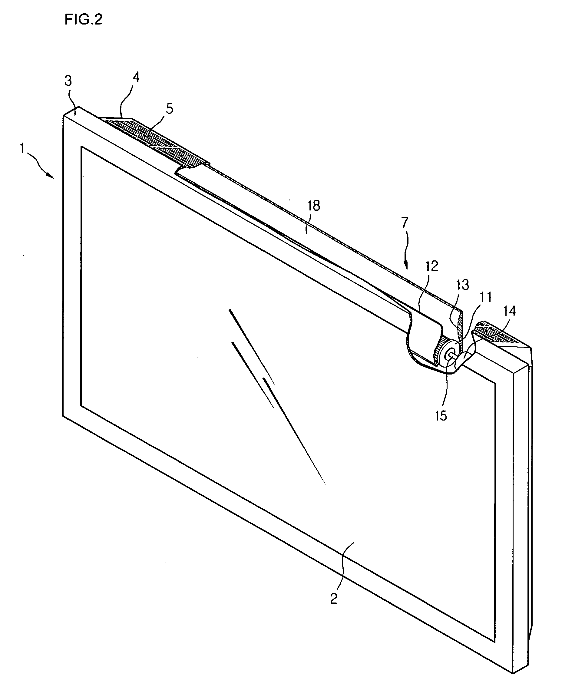
[0090] Referring to FIG. 10, a cross-flow fan 7 of this embodiment is different from that of FIG. 2. That is, the cross-flow fan 7 of this embodiment includes a motor 14 installed on a middle portion. Driving shafts 151 and 152 extend from opposite ends of the motor 14 and are connected to an impeller unit 10.

[0091] The impeller unit 10 includes left and right impellers 101 and 102. Therefore, the vibration or unstable operation, which may be caused when the impeller unit 10 is formed in a long single impeller, can be prevented.

[0092] The left and right impellers 101 and 102 are connected to the single motor 14 by the left and right driving shafts 151 and 152, respectively....


PUM


Abstract

There is provided a cooling apparatus for a flat display device. The cooling apparatus includes a flat display module, a front cover for protecting a front portion of the flat display module, a back cover for protecting a rear portion of the flat display module, an air inlet formed on a portion of the back cover to allow external air to be introduced into the back cover, an air outlet formed on another portion of the back cover and extending along a longitudinal length of the flat panel display module; a fan disposed inside the back cover and aligned with the air outlet formed on the back cover, and an air outlet channel formed in the back cover and aligned with the air outlet formed on the back cover, the air outlet having an effective exhaust area having a longitudinal length extending in a longitudinal direction of the flat display module.

Description

BACKGROUND OF THE INVENTION [0001] 1. Field of the Invention [0002] The present invention relates to a flat display device, and more particularly, a cooling apparatus for a flat display device, which can be operated with a low noise while quickly dissipating internal heat to an external side. [0003] 2. Description of the Related Art [0004] Unlike a cathode ray tube (CRT), a flat display uses a driving circuit arranged in a matrix pattern to differently excite pixels and thus realize an image. Recently, the flat display device has been widely used as it has advantageous in that it takes up a relatively small space. A variety of flat display modules such as a liquid crystal display (LCD), a field emission display (FED), a plasma display panel (PDP), and an electro-luminescence (EL) have been applied to the flat display device. [0005] The flat display device using the flat display module is reduced in a thickness as compared with the CRT. However, since a large number of heat-generatin...

Claims


Application Information

Patent Timeline
Patent Type & Authority Applications(United States)
IPC IPC(8): G06F1/20
CPCG06F1/1601G06F1/20H05K7/20972Y10S345/905
Inventor KIM, HONG KI
Owner LG ELECTRONICS INC
Why Eureka
Try Eureka