Capped tubes

a technology of capped tubes and caps, which is applied in the field of capped tubes, can solve the problems of substantial problems in maintaining the seal integrity of the cap to the tube, polypropylene, and a comparatively high coefficient of thermal expansion

Inactive Publication Date: 2007-05-10
ADVANCED BIOTECHNOLOGIES LTD
View PDF22 Cites 135 Cited by
  • Summary
  • Abstract
  • Description
  • Claims
  • Application Information

AI Technical Summary

Benefits of technology

[0023] According to a further aspect of the present invention there is provided a screw-capped tube for holding a liquid material therein, the tube having an open mouth at one end only and which is adapted to be closed by the screw cap, wherein at least a part of the cap that engages with the tube is formed of a material that is different from the co-operative engaging part of the tube whereby when the capped tube is subjected to a significantly colder thermal environment the tightness of fit between the cap and the tube is maintained and preferably will increase.

Problems solved by technology

However, where tubes of this type are to be used in extreme temperature environments and, in particular, in extreme low temperature environments such as for cryogenic storage in the gas phase of a liquid nitrogen cooled vessel, generally at or above −196° C., a characteristic of the construction of the tube and cap can cause substantial problems in maintaining the seal integrity of the cap to the tube.
The material most commonly used in construction of the tubes, polypropylene, has a comparatively high coefficient of thermal expansion and will contract quite substantially when subjected to a reduction in environmental temperature from around room temperature to −196° C. Contraction of the polypropylene material forming the mating threads of the screw-capped tube compromises the integrity of the screw engagement and undermines the sealing effectiveness of the cap.
A further problem area with screw capped tubes is the amount of handling time required to de-cap and re-cap them in use.
For high throughput programmes and programmes where multiple de-capping and re-capping steps are necessitated—e.g. where samples need to be taken from the tube at intervals or reagents / media added at intervals—the time taken to remove the cap and replace it can be a significant impediment to the efficiency of the programme.
For smaller screw capped cluster tubes, such as those that are generally of the order of 0.5 or 1 ml in capacity, the size of the screw cap is relatively small and the tubes generally densely arrayed (eg in a 96 tube cluster tube rack in a grid arrangement occupying a footprint of less than 12 cm by 8 cm), making access to individual caps awkward and giving handlers difficulty in de-capping and re-capping them in the racks.

Method used


Image

  • Capped tubes
  • Capped tubes
  • Capped tubes

Examples


Embodiment Construction

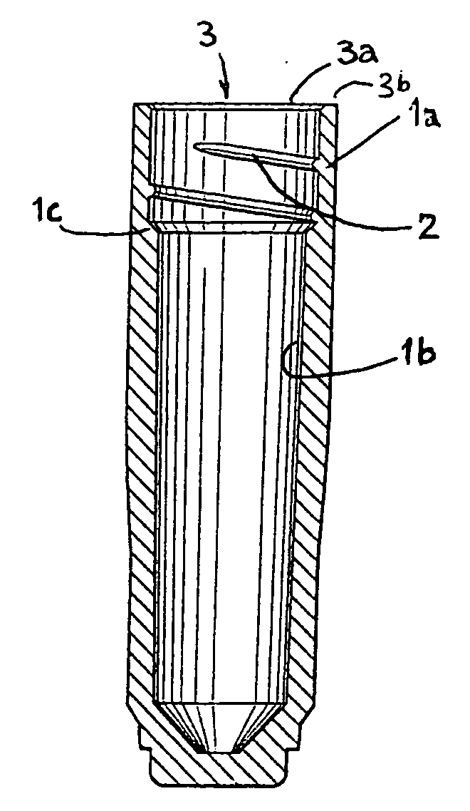
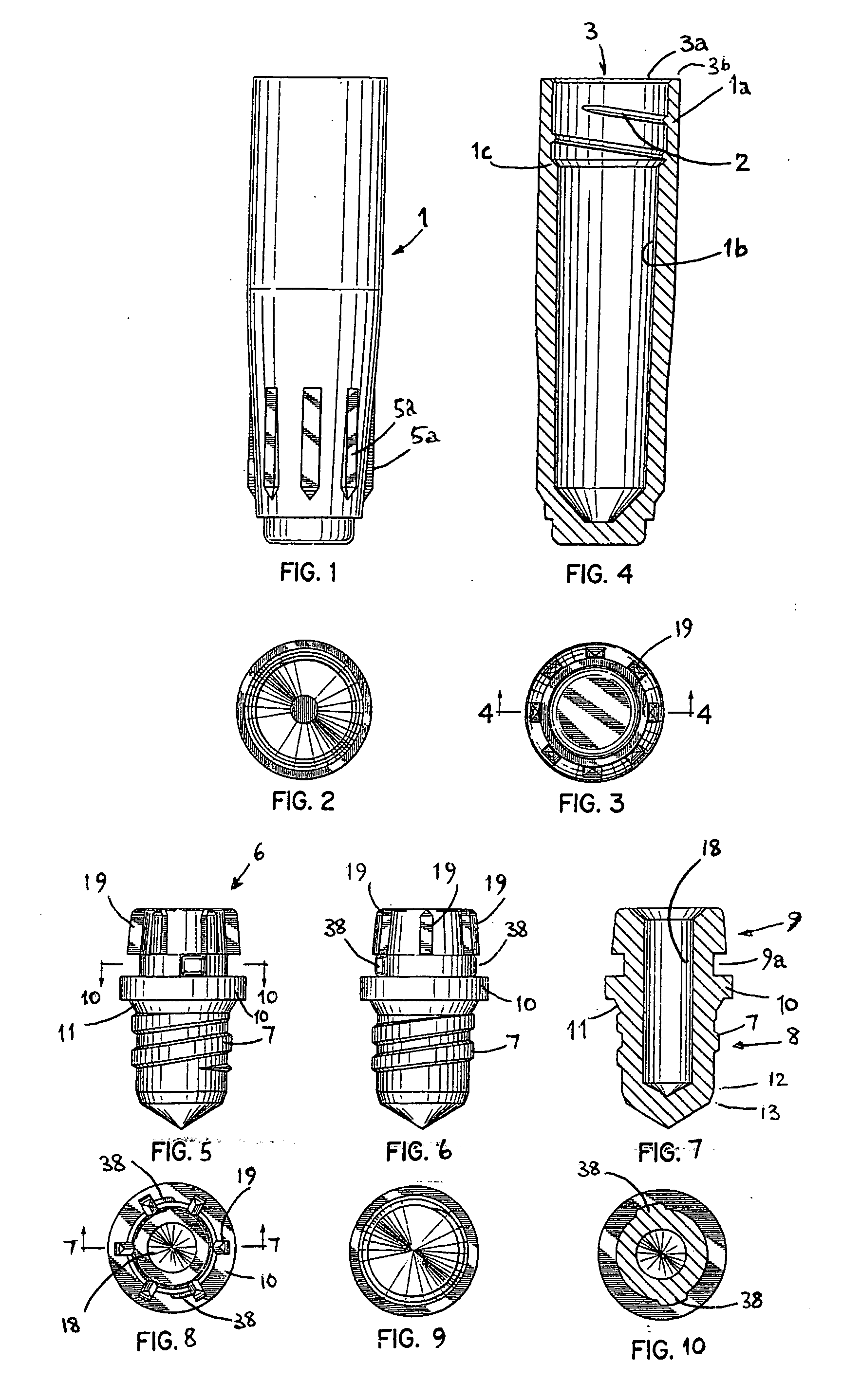
[0054] Referring to the Figures, the tube 1 shown in FIGS. 1 to 4 is moulded of polypropylene and having a screw thread formation 2 moulded at its upper end / mouth end 3. The rim of the opening of the tube 1 at the mouth end 3 has an upper end surface 3b and is recessed / part cutaway immediately around the opening to define a frusto-conical surface 3a at the entrance to the bore of the tube 1 against which an upper end of the cap 6 may seat.

[0055] From the mouth end 3 to the opposing closed base end 5 of the tube 1, the bore of the tube 1 tapers inwardly in stages. An upper portion 4 of the tube 1 that incorporates the screw thread formation 2 is of substantially uniform internal diameter but below this screw threaded portion 4 the bore is instepped 1c or begins to taper inwardly. The external profile of the tube also tapers inwardly towards the base end 5 and is provided with an array of longitudinally extending ribs / splines 5a around its outer circumference proximate the base end 5...


PUM


Abstract

In a first aspect the present invention provides a screw-capped tube for holding a liquid material therein, the tube having an open mouth at one end only which is adapted to be closed by the screw cap with an inner end of the screw cap extending into the open mouth of the tube, an opposing end of the cap to the inner end of the cap being provided with a circular cylindrical recess extending thereinto and whereof the cylindrical wall of the recess is free of splines, an outer circumferential surface of the cap being provided with a spline whereby the cap is adapted to co-operatively engage with a spline of a tool that will fit on to said opposite end of the cap for rotation of the cap by co-operative engagement of the spline of the tool with the spline of the cap. This arrangement increases versatility and ease in de-capping and re-capping of the tubes. Further aspects also assist with this and/or improve seal efficiency and help to avoid the need for O ring sealing for cryogenic uses and other uses.

Description

FIELD OF THE INVENTION [0001] The present invention concerns capped tubes such as are used in laboratories for holding liquid reagents or samples and is particularly applicable to screw-capped tubes, suitably cluster tubes, and especially suitably cryogenic tubes. BACKGROUND TO THE INVENTION [0002] In the modern life sciences laboratory one of the basic items of apparatus that has evolved markedly in recent years is the sample or reagent storage vessel. To cater for small sample or reagent volumes and facilitate high throughput, common characteristics of modern reagent / sample vessels are that they are generally moulded of plastics, very small, e.g. 0.5 ml capacity, and in the case of cluster tubes are adapted to be configured in high density arrangements of, for example, 48 or 96 tubes configured in a matrix array and rack mounted. Commonly, the tubes are of polypropylene and for those tubes that are provided with caps, both the tube and the cap are generally of polypropylene. [0003...

Claims


Application Information

Patent Timeline
Patent Type & Authority Applications(United States)
IPC IPC(8): B01L3/00
CPCB01L3/50825B01L3/50855B01L9/06B01L2200/025B01L2300/0829
Inventor COULLING, JEFFREY LEONARDHARRISON, CLIVE IAN
Owner ADVANCED BIOTECHNOLOGIES LTD
Why Eureka
Try Eureka