Delivery of agents to tissue

a technology of tissue and agents, applied in the field of tissue delivery, can solve the problems of indeterminate amount of injectate squirting or leaking out the needle track, tissue becomes relatively hard and tense, and is presumably wasted

Inactive Publication Date: 2007-05-10
BAYER HEALTHCARE LLC +1
View PDF55 Cites 106 Cited by
  • Summary
  • Abstract
  • Description
  • Claims
  • Application Information

AI Technical Summary

Benefits of technology

[0021] In one aspect, the present invention provides a system for injecting an injectate into patient, including: a first pressurizable container for holding the injectate; a patient interface in fluid connection with the first pressurizable container, the patient interface being adapted to pass the injectate into tissue of the patient; a powered injector in operative connection with the first pressurizable container to pressurize the injectate; a controller system in operative connection with powered injector; and a stereotactic localization frame adapted to be placed in operative connection with the patient interface to assist in controlling localization of the patient interface.

Problems solved by technology

A challenge is presented in that when the heart is contracting, during systole, the tissue becomes relatively hard and tense.
It is very difficult for a human to time and control a hand injection so that the proper volume is injected all in one period of diastole.
In practice, an indeterminate amount of the injectate can squirt or leak out the needle track and is presumably wasted.
These results can also be difficult to achieve with current manual injection practices.
With the current state of practice, scar tissue is not injected or treated because it does not respond well, and the growth that does occur can sometimes create dangerous electrical conduction abnormalities.
However the simplicity is misleading.
Many of the parameters of the injection are not and cannot be controlled or even repeated by that doctor, let alone by other doctors.
Flow rate is, for example, very difficult to control manually, especially at low flow rates.
The stick slip friction of normal syringes exacerbates this problem.
Volume accuracy depends upon manual reading of gradations, which is physically difficult while squeezing the syringe and susceptible to human perceptual or mathematical errors.
The use of common infusion pumps limits delivery to generally slow and very simple fluid deliveries.
Infusion pumps have no ability to provide automatic response or action to the injection based upon any physiological or other measurement or feedback.
In clinical trials, this variation is undesirable because it increases the number of patients and thus cost and time needed to establish efficacy.
In long term therapeutic use, such variation remains undesirable as some people can receive suboptimal treatment.
Current manual approaches (as summarized above and in connection with FIG. 1A) do not address all of the needs required by new procedures.
For example, there are no good methods for ensuring the parameters of cell viability, including spatial distribution, cell quantity, metabolic and electrical activity, in real time during the entire implantation procedure.
Deleterious effects of flow of cells through fluid paths are also not well addressed in current techniques.
As the tapered sections of the male 1a and female 1b connectors mate, a dead space is created as indicated by 1c. In addition, the sharp transition in the fluid path at the end of the male luer, as indicated at 1d, can create turbulence and increase shear stress in the fluid and on the cells, resulting in cell damage or even death.
Moreover, similar problems exist in commonly used fluid path elements other than connectors.
Although the '720 patent discloses methods of injecting liquid medications based on a biomechanical model of tissue, it does not address problems unique to the delivery of complex slurries of fragile neural cells.
However, the '274 patent does not describe how the elements of a controlled cell storage system work together with an injection system to guarantee delivery of viable cells of correct dosage and associated growth factors into tissues of the CNS.

Method used


Image

  • Delivery of agents to tissue
  • Delivery of agents to tissue
  • Delivery of agents to tissue

Examples


Embodiment Construction

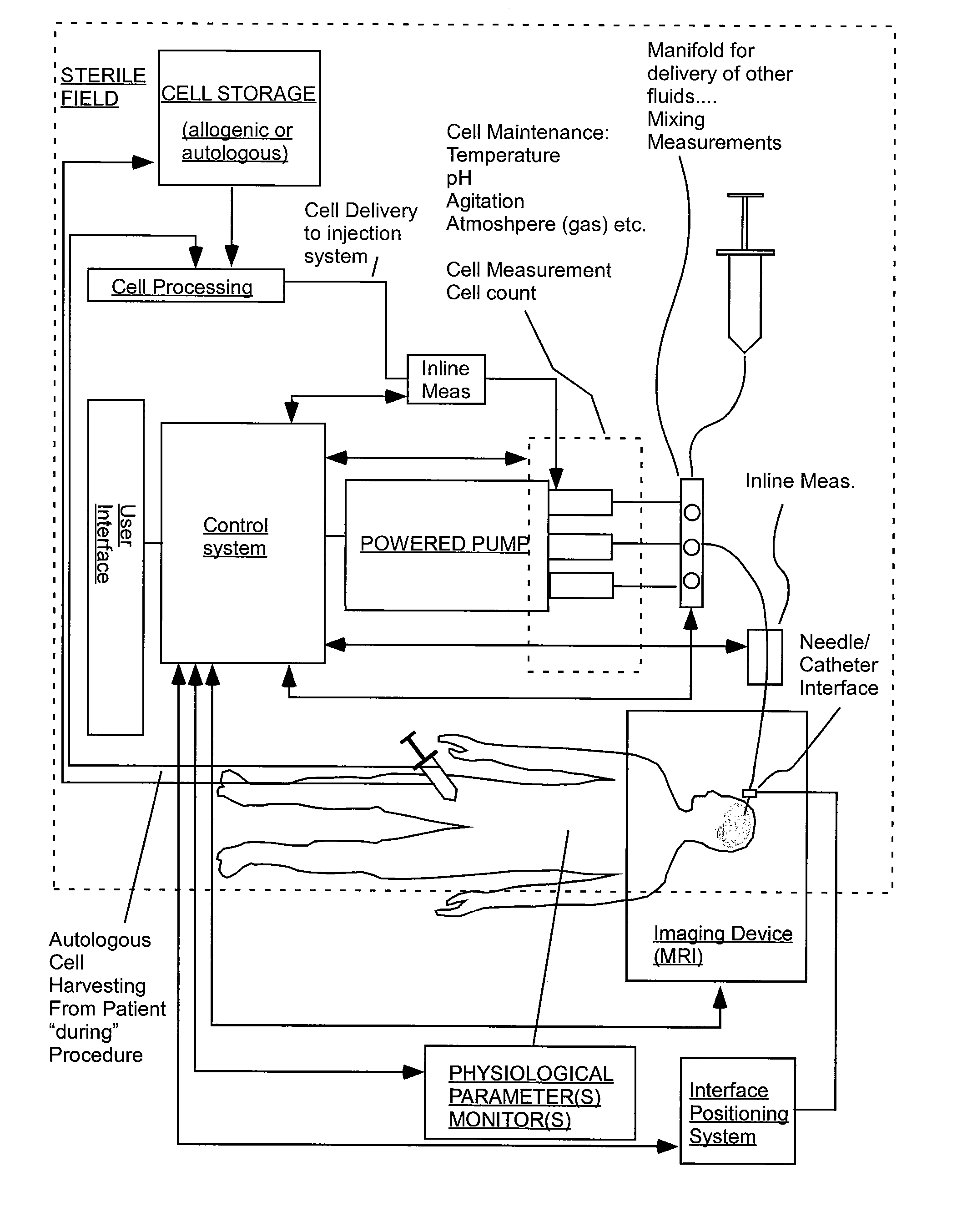
[0119] FIGS. 2 sets forth several embodiments of systems of the present invention for use in delivery of an injectate or injection fluid, and particularly an injection fluid containing cells, to a brain of a patient. FIG. 3 sets forth several embodiments of systems of the present invention for delivery of an injection fluid, and particularly cells, to the heart of a patient. Several embodiments of the present invention are discussed below in detail with respect to delivery of cells to the brain or external heart of a patient. However, one skilled in the art appreciates that the devices, systems and methods of the present invention can be used to deliver many different types of substances to many different tissues, internal to the body as well as to the skin. Moreover, the devices, systems and methods of the present invention are applicable to open surgery or endoscopic needle-based deliveries as well as to catheter-based deliveries.

[0120] The systems of FIGS. 2 and 3 are similar in...


PUM

PropertyMeasurementUnit
diameteraaaaaaaaaa
volumeaaaaaaaaaa
volumeaaaaaaaaaa

Abstract

A system for injecting an injectate into patient includes a first pressurizable container for holding the injectate; a patient interface in fluid connection with the first pressurizable container, the patient interface being adapted to pass the injectate into tissue of the patient; a powered injector in operative connection with the first pressurizable container to pressurize the injectate; a controller system in operative connection with powered injector; and a stereotactic localization frame adapted to be placed in operative connection with the patient interface to assist in controlling localization of the patient interface. A system for processing cells (and/or other injectate components) includes a container and a plunger adapted to be slidably positioned within the container. The system includes at least one inlet port through which a fluid can enter the system and at least one effluent port through which an effluent can exit the system. The plunger section forms a sealing engagement with the inner wall of the container such that rearward motion of the plunger is adapted to draw fluid into the system via the inlet and forward motion of the plunger is adapted to force effluent out of the system via the effluent port.

Description

CROSS-REFERENCE TO RELATED APPLICATION [0001] This application claims benefit of U.S. Provisional Patent Application Ser. No. 60 / 771,206, filed Feb. 7, 2006, U.S. Provisional Patent Application Ser. No. 60 / 742,224, filed Dec. 5, 2005, and U.S. Provisional Patent Application Ser. No. 60 / 734,035, filed Nov. 4, 2005, the disclosures of which are incorporated herein by reference.BACKGROUND OF THE INVENTION [0002] The present invention relates to the delivery of agents such as therapeutic agents to tissue and, particularly, to the delivery of cells to tissue. [0003] The following information is provided to assist the reader to understand the invention disclosed below and the environment in which it will typically be used. The terms used herein are not intended to be limited to any particular narrow interpretation unless clearly stated otherwise in this document. References set forth herein may facilitate understanding of the present invention or the background of the present invention. T...

Claims


Application Information

Patent Timeline
Patent Type & Authority Applications(United States)
IPC IPC(8): A61M31/00A01N1/02C12M1/12C12M1/24B65D25/04A01N1/00C12M3/00B65D1/24B65D1/36B65D57/00B65D85/00
CPCA61M5/142A61M5/1723A61M31/005G06F19/3468A61J1/1443A61J1/1475A61M5/3145G16H20/17A61J1/1456B01L3/502B01L2300/044B01L2300/0681
Inventor UBER, ARTHUR E. IIITROMBLEY, FREDERICK W. IIIGELBLUM, EUGENE A.RHINEHART, EDWARD J.REILLY, DAVID M.CEDARHOLM, PAGECOWAN, KEVIN P.TROCKI, MARKHIRSCHMAN, ALAN D.
Owner BAYER HEALTHCARE LLC
Why Eureka
Try Eureka